
2MXL18QMVJUA Installation Manual


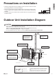
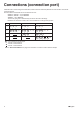
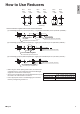
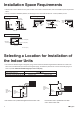

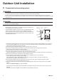
Table Of Contents
- Safety Considerations
- Accessories
- Precautions for Selecting a Location
- Precautions on Installation
- Outdoor Unit Installation Diagram
- Connections (connection port)
- How to Use Reducers
- Installation Space Requirements
- Selecting a Location for Installation ofthe Indoor Units
- Outdoor Unit Installation
- 1. Installing the outdoor unit
- 2. Drain work
- 3. Refrigerant piping
- 4. Pressure test and evacuating system
- 5. Refilling refrigerant
- 6. Charging with refrigerant
- 7. Refrigerant piping work
- 8. Flaring the pipe end
- Wiring
- Priority Room Setting
- Night Quiet Mode setting
- COOL/ HEAT mode lock [S15]
- Pump Down Operation
- Trial Operation and Testing
- 1. Wiring error check
- 2. Trial operation and testing
- 3. Test items

8■English
Outdoor Unit Installation
1. Installing the outdoor unit
1) When installing the outdoor unit, refer to “Precautions for Selecting a Location” on page 3 and the “Outdoor Unit
Installation Diagram” on page 4.
2) If drain work is necessary, follow the procedures below.
2. Drain work
CAUTION
In cold areas, do not use a drain socket, drain caps (1,2)
and a drain hose with the outdoor unit. (Drain water may
freeze, impairing heating performance.)
• Ifthedrainportiscoveredbyamountingbaseoroor
surface, place additional foot bases of at least 1-1/4
inch (30mm) in height under the outdoor unit’s feet.
1) Attach
C
drain cap (1) and
D
drain cap (2).
2) Attach
B
drain socket.
• When attaching
B
drain socket to the bottom
frame, make sure to connect the drain hose to the
drainsocketrst.
3. Refrigerant piping
CAUTION
• Usethearenutxedtothemainunit.(Thisistopreventthearenutfromcrackingasaresultofdeteriorationovertime.)
• Topreventgasleakage,applyrefrigerationoilonlytotheinnersurfaceoftheare.(UserefrigerationoilforR410A.)
• Useatorquewrenchwhentighteningthearenutstopreventdamagetothearenutsandgasleakage.
• Alignthecentersofbotharesandtightenthearenuts3or4turnsbyhand,thentightenthemfullywithaspanneranda
torque wrench.
Do not apply refrigeration
oil to the outer surface.
Flare nut
Apply refrigeration
oil to the inner
surface of the flare.
Do not apply refrigeration oil to
the flare nut to avoid tightening
with excessive torque.
Apply oil
Torque wrench
Piping union
Flare nut
Spanner
Tighten
Flare nut tightening torque
φ1/4 inch (6.4mm)
φ3/8 inch (9.5mm)
φ1/2 inch (12.7mm)
φ5/8 inch (15.9mm)
10-1/2 – 12-3/4ft • lbf (14.2-17.2N • m)
24-1/8 – 29-1/2ft • Ibf (32.7-39.9N • m)
36-1/2 – 44-1/2ft • lbf (49.5-60.3N • m)
45-5/8 – 55-5/8ft • lbf (61.8-75.4N • m)
Width across flats
Valve cap tightening torque
Service port cap tightening torque
8 –10-7/8ft • lbf
(10.8-14.7N • m)
11/16 inch (17mm)
10-1/2 – 12-5/8ft • lbf
(14.2-17.2N • m)
3/4 inch (19mm)
12-5/8–15-3/8ft • lbf
(17.1-20.9N • m)
7/8 inch (22mm)
16–20-1/4ft • lbf
(21.6-27.4N • m)
1-1/16 inch (27mm)
35-3/8 – 44-1/8ft • lbf
(48-59.8N • m)
Bottom frame
Drain cap
Pinch the bottom
frame in.
Drain cap (1)
Drain cap (2)
D
Drain cap (2)
Air outlet side
B
Drain
socket
C
D
Bottom frame
Drain socket
Hose (available commercially,
inner dia. 5/8 ” (16mm))
B
English
01_EN_3P379970-11C.indd 8 10/18/2019 9:20:06 AM