
BPMKS049A3U Installation Manual

English 9
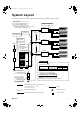
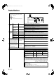
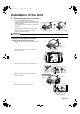
6) Attach the printed circuit board and electrical wiring box
cover to the other side and secure with the screws.
2.
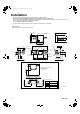
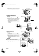
Ceiling-suspended type
Procedure:
1) Fix the furnished hanger metal with two screws.
(4 locations in total)
2) Using an insert-hole-in-anchor, hang the hanging bolt.
3) Install a hexagon nut and a flat washer (field supply) to
the hanging bolt as shown in the figure in the below,
and lift the unit to hang on the hanger metal.
4) After checking with a level that the unit is level, tighten
the hexagon nut.
* The tilt of the unit should be within ±5° in front/ back
and left/right.
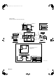
3.
Wall-mounted type
Procedure:
1) Fix the furnished hanger metal with two screws.
(4 locations in total)
2) Create a gap with the wall and screw in the temporary
screws (M5, field supply), and hang the BP unit.
3) After checking with a level that the unit is level, fix the
unit with screws (M5, field supply).
* The tilt of the unit should be within ±5° in front/ back
and left/right.
CAUTION
• Be sure to install the unit with the top surface up.
• Do not install near bedrooms. The sound of refrigerant
flowing through the piping may sometimes be audible.
Electrical
wiring box
cover
Insert the
tabs fully.
Printed circuit board
Top surface of the unit
Ceiling side
Screws
C
Hanger metal
B
B C
Flat washer
0.59-0.79
(15-20)
Hanging bolt
Nut
BP unit
Hanging bolt
(M8 or M10)
Hexagonal nut
(M8 or M10)
Flat washer
Hanger metal
B
Screws
(M5, field supply)
Screws
(M5, field supply)
Temporary screws:
attach and then hang the
unit on them. (2 screws)
: screw for fixing. (4 locations)
Temporary screw (M5, field supply):
Screw in temporarily after opening
a slight gap with the wall.
Screws
C
Screws
C
Hanger metal
B
Hanger
metal
B
B C
01_EN_3P329626-1.fm Page 9 Friday, November 9, 2012 11:10 AM