
BPMKS049A3U Installation Manual
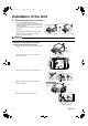


10 English
Connection of Refrigerant Piping
<Make sure to perform heat insulation work for both gas piping and liquid piping. If not insulated, water leakage may occur. For gas
piping, use a heat insulation material with a heat-resistant temperature of 212°F (100°C) or more. Condensation may be formed on
the surface of the heat insulation material.>
<Before installation, make sure that the refrigerant type is R410A. (Wrong refrigerant types prevent normal operation.)>
• The refrigerant is filled in the outdoor unit.
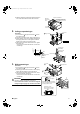
• When connecting a pipe to the unit body or removing it, be sure to use a spanner and torque wrench. (See Fig. [1].)
• For the work dimension and the tightening torque of the flare section, see <Table-1>.
• When connecting a flare nut, apply the refrigerant oil used for the compressor of the outdoor unit (or similar product) to the flare
section (only the inner surface), and screw the nut three or four times initially by hand. (See Fig. [2].)
• If the connecting piping is bent above the ceiling, it should be bent as loosely as possible.
If it is bent sharply, the heat insulation material may be compressed at the bent section, causing condensation.
• Be sure to use the flare nuts included with the unit body.
CAUTION
• Do not mix air or other gases than the specified refrigerant into the refrigeration cycle.
• If the refrigerant gas has leaked during the work, provide ventilation.
• Excessive tightening can cause a fracture of the flare nut and leakage of the refrigerant.
• Be sure to perform heat insulation for the field piping including the pipe connection in the unit.
Exposure of piping can cause condensation or burn injury.
• At the time of flare connection, apply the refrigerant oil used for the compressor of the outdoor unit (or similar product) to the
flare section. (See Fig. [2].)
• To prevent dirt, water content, and dust from entering the pipes, provide protection for the pipes using pinches or tape.
<Table-1>
• Alphabets (A, B, and C) corresponding to the room to be
connected with each indoor unit are inscribed on the main body
of the BP unit. (Figure on the right)
A: Refrigerant pipe connection port for “Room A”
B: Refrigerant pipe connection port for “Room B”
C: Refrigerant pipe connection port for “Room C”
CAUTION
• Be sure to put a mark on every refrigerant piping (such as
liquid pipe and gas pipe) so that to which room each indoor
unit belongs can be known clearly. (Example: A, B, C)
Pipe size Tightening torque
Work dimension for flare
section: A
Flare shape
φ1/4 inch
(φ6.4mm)
10.4-12.7ft·lbf
(14.2-17.2N·m)
0.343-0.358 inch
(8.7-9.1mm)
φ3/8 inch
(φ9.5mm)
24.1-29.4ft·lbf
(32.7-39.9N·m)
0.504-0.519 inch
(12.8-13.2mm)
φ1/2 inch
(φ12.7mm)
36.5-44.5ft·lbf
(49.5-60.3N·m)
0.638-0.653 inch
(16.2-16.6mm)
φ5/8 inch
(φ15.9mm)
45.6-55.6ft·lbf
(61.8-75.4N·m)
0.760-0.775 inch
(19.3-19.7mm)
A
45˚±2˚
90˚±2˚
R0.016-0.031 inch
(R0.4-0.8mm)
Torque wrench
Flare nut
Spanner
Piping union
Fig. [1] Fig. [2]
Refrigerant oil used for the compressor
of the outdoor unit (or similar product)
Room B
(Gas pipe)
Room A
(Gas pipe)
Room C
(Gas pipe)
Room B
(Liquid pipe)
<Indoor unit side (for 3 rooms)>
Room C
(Liquid pipe)
Room A
(Liquid pipe)
Hanger metal
B
01_EN_3P329626-1.fm Page 10 Friday, November 9, 2012 11:10 AM