
BPMKS049A3U Installation Manual


English 15
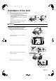
5) Follow the instructions on the wiring nameplate to connect the connection wires of indoor/outdoor units to terminal block
numbers (1, 2, 3, F
1
and F
2
). Always fix each ground wire separately with a ground screw. (See the figure below.)
Example <For 3 rooms>
WARNING
• Do not use tapped wires,stranded wires, extensioncords, or starbust connections, as they may cause overtheating, electrical
shock, or fire.
CAUTION
• Pass all inter-unit wires through wire retainers. In
addition, secure the wires with binding band to
prevent them from coming out if pulled on from the
outside.
• When connecting the inter-unit wires to the terminal
block using a single core wire, be sure to perform
curling.
Problems with the work may cause heat and fires.
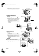
How to ground the shield for transmission
wires
• Fold back the grounding section of the shield for the
transmission wire and secure it with the copper foil
section of the wire retainer.
F1
F2
L2
L1
44
44P
Wire
retainer
Inter-unit wire for
indoor units.
(AWG 16-14)
When wire length exceed 33ft (10m),
use AWG 14 wires.
Power supply wire
(AWG 16-14)
Wire retainer
2
1
3
2
1
3
2
1
3
Room A
Room B
Room C
Ground
Safety
breaker
15A
Ground
fault circuit
interrupter
Power supply
60Hz 208/230V
Secure the wires with J binding
band to prevent them from coming
out if pulled on from the outside.
Transmission wire
(To other BP unit: F
1, F2)
Transmission wire (To other BP unit:
F
1, F2 or to outdoor unit: F1, F2)
* Fix each wire
separately.
CAUTION
Mistakenly connecting
the power supply to this
terminal block could
cause control operating
malfunctions.
Sheathed two-core cables
of AWG 18-16
Binding band
J
J
Secure the wires with J binding
band to prevent them from coming
out if pulled on from the outside.
Binding band
J
J
4
Good Wrong
Wire retainer
Binding
band
J
J
Screw
Shield grounding Transmission wire
Wire retainer
Binding
band
J
01_EN_3P329626-1.fm Page 15 Friday, November 9, 2012 11:10 AM