
BPMKS049A3U Installation Manual


16 English
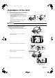
Connecting the Wiring
6) Return the electrical wiring box cover to its original position, and fix it with the
screws.
7) Fix the conduit mounting plate (cover) with the screw.
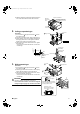
Operating Test
Follow the “Operating test” as described in the installation manual of the outdoor unit.
If the BP unit does not operate normally during the test run, the error can be checked on the remote controller display for the indoor
unit.
Error codes displayed on the remote controller
The BP Unit
Simple diagnosis can be done using the LEDs on the BP unit’s circuit board.
For details, see the label on the inside of the BP unit’s electrical wiring box cover.
Malfunction code Nonconformity during installation Remedial action
A9 Electric expansion valve connector not connected (BP unit)
Please contact your dealer.E2 Printed circuit board faulty (BP unit)
J0 Liquid and gas thermistor faulty (BP unit)
U4 Transmission error between BP unit and indoor unit
Connect correctly the interconnections
between BP unit and indoor unit.
U9 Transmission error between outdoor unit and other BP unit
Connect correctly the interconnections
between outdoor and other BP unit.
UJ
Transmission error between outdoor unit and this BP unit
connecting with the indoor unit of error code displayed
Connect correctly the interconnections
between outdoor and this BP unit
connecting with the indoor unit of error
code displayed.
Screw (M4)
Install the electrical wiring box cover.
Screw (M4)
Conduit mounting
plate (cover)
H
C
H
01_EN_3P329626-1.fm Page 16 Friday, November 9, 2012 11:10 AM