
BPMKS049A3U Installation Manual


6 English
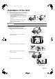
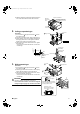
Installation
• This unit may be installed suspended from the ceiling or mounted on the wall.
• Be sure to install the unit with the top surface facing upward as shown in the diagram.
• Be sure to leave a 26 inch (650mm) square opening for maintenance and inspection as shown in the diagram below, for both
ceiling-suspended installation and wall-mounted installation.
• This unit “does not require drain treatment”.
• The inclination of top surface must be within ±5 degrees forward or back or to the sides.
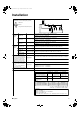
(product dimensions and attachment bolt pitch)
1 (25)
4-7/16
(113)
Wall-mounted
1-3/4
(45)
2-1/4
(57)
3-3/4
(95)
(12 (304))
2-7/8
(73.5)
7/8 (23)
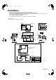
Room A
Room B
Indoor unit side Outdoor unit side
Wire retainer
(7-1/16 (180))
(24-11/16 (628))
11-9/16 (294)
6-9/16 (167)
7-3/4 (197)
4-1/4
(107)
12-11/16 (322)
Suspension bolt pitch
(26-11/16 (678))
10 (254)
(12 (304))
1 (25)
2-7/8
(73.5)
6-9/16 (167)
2-φ5/8 (φ15.9)
flare connection
2-φ1/4 (φ6.4)
flare connection
Terminal block
(for power supply)
Terminal block
(for room A)
Terminal block
(for room B)
Terminal block
(for transmission)
φ3/8 (φ9.5)
flare connection
φ5/8 (φ15.9)
flare connection
Ground (M4)
7/8 (23)
Suspension bolt pitch
Manufacturer’s label
4-Suspension bolt
(M8 or M10)
For 2 rooms
Indoor unit
side piping
Top surface
Electrical
wiring box
Wire
retainer
Wire
retainer
7-9/16 (192)
(11-9/16 (294))
7-9/16 (192)
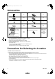
Installation restrictions
(Installation and servicing spaces)
26×26 (650×650) inspection port
Provide an inspection
port for servicing and
maintenance.
(servicing spaces)
12 (300) or more
(servicing spaces)
15-3/8 (390) or more
(servicing spaces)
15-3/8 (390) or more
Minimum bend radius
Minimum bend radiusPipe size
φ1/4 (φ6.4)
1-3/16 (30) or more
φ3/8 (φ9.5)
1-15/16 (50) or moreφ5/8 (φ15.9)
1-9/16 (40) or moreφ1/2 (φ12.7)
unit: inch (mm)
01_EN_3P329626-1.fm Page 6 Friday, November 9, 2012 11:10 AM