English Français INSTALLATION MANUAL R410A Split Series Installation manual Manuel dinstallation Manual de instalación MODELS 3MXS24RMVJU 4MXS36RMVJU 3MXL24RMVJU 3MXS24RMVJUA 4MXS36RMVJUA 3MXL24RMVJUA Español DAIKIN ROOM AIR CONDITIONER
Contents Safety Considerations ..................................... 1 Accessories ...................................................... 3 Precautions for Selecting a Location ............ 3 Precautions on Installation ............................. 4 3. Refrigerant piping......................................................... 8 4. Pressure test and evacuating system........................... 9 5. Refilling refrigerant....................................................... 10 6.
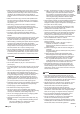
• Make sure that all wiring is secured, that specified wires are used, and that no external forces act on the terminal connections or wires. Improper connections or installation may result in fire. • When wiring, position the wires so that the electrical wiring box cover can be securely fastened. Improper positioning of the electrical wiring box cover may result in electric shock, fire, or the terminals overheating. • Before touching electrical parts, turn off the unit.
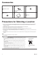
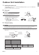
Accessories C Drain cap (1) B Drain socket A Installation manual 1 1 6 This is at the bottom of the packaging. E Reducer assy D Drain cap (2) 3 1 1 F Warranty Precautions for Selecting a Location 1) Choose a place solid enough to bear the weight and vibration of the unit, where the operating sound will not be amplified. 2) Choose a location where the hot air discharged from the unit or the operating sound will not cause a nuisance to the neighbors of the user.
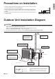
3/4” (20mm) • Check the strength and level of the installation surface so that the unit does not cause any operating vibrations or noise after installation. • Fix the unit in place securely using foundation bolts, as in the figure. (Prepare 4 sets of 5/16 inch (M8) or 3/8 inch (M10) foundation bolts, nuts and washers; all separately available.) • It is best to screw in the foundation bolts until their ends are 3/4 inch (20mm) from the foundation surface.
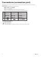
Connections (connection port) Install the indoor unit according to the table below, which shows the relationship between the class of indoor unit and the corresponding port. The total indoor unit class that can be connected to this unit: 2MXS18*, 2MXL18* – Up to 24000 Btu 3MXS24*, 3MXL24* – Up to 39000 Btu 4MXS36* – Up to 48000 Btu The line set piping size is determined by the size of the indoor unit fittings. Reducers are used at the outdoor unit to accommodate the correct gas line pipe size.
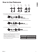
No.1 φ5/8” φ1/2” No.2 φ1/2” φ3/8” No.3 φ5/8” φ1/2” Gasket (1) No.4 φ1/2” φ3/8” Gasket (2) No.5 φ5/8” φ3/8” English How to Use Reducers No.6 φ5/8” φ3/8” Reduce and gasket • Use the reducers supplied with the unit as described below. (1) Connecting a pipe of φ1/2 inch (12.7mm) to a gas pipe connection port for φ5/8 inch (15.9mm) : No. 1 Be sure to attach the gasket. Inter-unit piping No. 3 Flare nut (for φ5/8 inch (15.
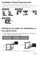
Installation Space Requirements • Position the unit on a horizontal surface. Any tilt in the unit should be 3° or less to the horizontal. • Where a wall or other obstacle is in the path of outdoor unit’s intake or exhaust airflow, follow the installation space requirements below. • For any of the below installation patterns, the wall height on the outlet side should be 47-1/4 inch (1200mm) or less.
1. English Outdoor Unit Installation Installing the outdoor unit 1) When installing the outdoor unit, refer to “Precautions for Selecting a Location” on page 3 and the “Outdoor Unit Installation Diagram” on page 4. 2) If drain work is necessary, follow the procedures below. 2. Drain work CAUTION C Drain cap (1) D Drain cap (2) In cold areas, do not use a drain socket, drain caps (1,2) and a drain hose with the outdoor unit. (Drain water may freeze, impairing heating performance.
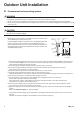
Outdoor Unit Installation 4. Pressure test and evacuating system WARNING • • • • Make sure that air or any matter other than refrigerant (R410A) does not get into the refrigeration cycle. If refrigerant gas leaks should occur, ventilate the room as soon and as much as possible. R410A, as well as other refrigerants, should always be recovered and never be released directly into the environment. Use a vacuum pump for R410A exclusively.
English 5. Refilling refrigerant Check the type of refrigerant to be used on the machine nameplate. Precautions when adding R410A Fill from the liquid pipe in liquid form. R410A is a mixed refrigerant, so adding it in gas form may cause the refrigerant composition to change, preventing normal operation. 1) Before filling, check whether the cylinder has a siphon attached or not. (It should have something like “liquid filling siphon attached” displayed on it.
Outdoor Unit Installation 7. Refrigerant piping work 7-1. Cautions on pipe handling • Protect the open end of the pipe from dust and moisture. • All pipe bends should be as gentle as possible. Use a pipe bender for bending. Rain If no flare cap is available, cover the flare mouth with tape to keep dirt and water out. 7-2. Selection of copper and heat insulation materials When using commercial copper pipes and fittings, observe the following: • Insulation material: Polyethylene foam Heat transfer rate: 0.
English Wiring WARNING • Do not use tapped wires, extension cords, or starburst connections, as they may cause overheating, electric shock, or fire. • Do not use locally purchased electrical parts inside the product. (Do not branch the power for the drain pump, etc., from the terminal block.) Doing so may cause electric shock or fire. • The circuit must be protected with safety devices in accordance with local and national codes, i.e. a circuit breaker.
Wiring [Wiring procedure] 1) Strip the insulation from the wire (3/4inch (20mm)). 2) Connect the inter-unit wires between the indoor and outdoor units so that the terminal numbers match. Tighten the terminal screws securely. It is recommended that a slot-head screwdriver be used to tighten the screws. 3) Be sure to match the symbols for wiring and piping. 4) Pull the wire lightly to make sure that it does not disconnect.
English Priority Room Setting • To use priority room setting, initial settings must be made when the unit is installed. Explain the priority room setting, as described below, to the user, and confirm whether or not the user wants to use priority room setting. Setting it in the guest and living rooms is convenient. About the priority room setting function The indoor unit for which priority room setting is applied takes priority in the following cases.
Night Quiet Mode setting • If night quiet mode is to be used, initial settings must be made when the unit is installed. Explain night quiet mode, as described below, to the user, and confirm whether or not the user wants to use night quiet mode. About night quiet mode The night quiet mode function reduces operating noise of the outdoor unit at nighttime. This function is useful if the user is worried about the effects of the operating noise on the neighbors.
In order to protect the environment, be sure to pump down when relocating or disposing of the unit. 1) Remove the valve cap from liquid stop valve and gas stop valve. 2) Carry out forced cooling operation. 3) After 5 to 10 minutes, close the liquid stop valve with a hexagonal wrench. 4) After 2 to 3 minutes, close the gas stop valve and stop forced cooling operation. 5) Attach the valve cap once procedures are complete.
Trial Operation and Testing • Before starting the trial operation, measure the voltage at the primary side of the circuit breaker. • Check that all liquid and gas stop valves are fully open. • Check that piping and wiring all match. The wiring error check can be conveniently used for underground wiring and other wiring that cannot be directly checked. However, if the outside air temperature is 41°F (5°C) or less , the wiring error check function will not operate. 1.
English 2. Trial operation and testing • During the trial operation, first check the operation of each unit individually. After this, check the simultaneous operation of all indoor units. Check both COOL and HEAT operations. 2-1. Measure the supply voltage and make sure that it is within the specified range. 2-2. In COOL operation, select the lowest programmable temperature; in HEAT operation, select the highest programmable temperature. 2-3.
Two-dimensional bar code is a manufacturing code.