
3MXL24RMVJUA Installation Manual
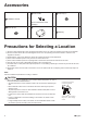
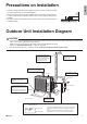
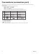
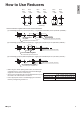
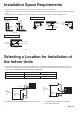
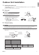
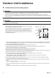
Table Of Contents
- Safety Considerations
- Accessories
- Precautions for Selecting a Location
- Precautions on Installation
- Outdoor Unit Installation Diagram
- Connections (connection port)
- How to Use Reducers
- Installation Space Requirements
- Selecting a Location for Installation ofthe Indoor Units
- Outdoor Unit Installation
- 1. Installing the outdoor unit
- 2. Drain work
- 3. Refrigerant piping
- 4. Pressure test and evacuating system
- 5. Refilling refrigerant
- 6. Charging with refrigerant
- 7. Refrigerant piping work
- 8. Flaring the pipe end
- Wiring
- Priority Room Setting
- Night Quiet Mode setting•
- COOL/ HEAT mode lock [S15]
- Pump Down Operation
- Trial Operation and Testing
- 1. Wiring error check
- 2. Trial operation and testing
- 3. Test items

9 ■English
Outdoor Unit Installation
4. Pressure test and evacuating system
WARNING
• Make sure that air or any matter other than refrigerant (R410A) does not get into the refrigeration cycle.
• If refrigerant gas leaks should occur, ventilate the room as soon and as much as possible.
• R410A, as well as other refrigerants, should always be recovered and never be released directly into the environment.
• UseavacuumpumpforR410Aexclusively.Usingthesamevacuumpumpfordifferentrefrigerantsmaydamagethevacuum
pump or the unit.
CAUTION
Itishighlyrecommendedthatyoudonotopen/closethestopvalveswhentheoutdoortemperatureisbelow−5°F(−21°C)as
this may result in refrigerant leakage.
• When piping work is complete, it is necessary to perform a pressure test
and evacuate system with a vacuum pump.
• If using additional refrigerant, purge the air from the refrigerant pipes and
indoor unit using a vacuum pump, then charge additional refrigerant.
• Useahexagonalwrench(3/16inch(4mm))tooperatethestopvalverod.
• All refrigerant pipe joints should be tightened with a torque wrench to the
speciedtighteningtorque.
Compound
pressure gauge
Pressure
meter
High-pressure
valve
Low-pressure
valve
Vacuum pump
Service port
Liquid
stop
valve
Valve caps
Gas stop valve
Charging
hoses
Gauge
manifold
1) Pressurize the liquid pipe and gas pipe from the service ports of each stop valve to 550psi (3.8MPa) (do not pressurize
more than 550psi (3.8MPa)) for 1 hour minimum, 24 hours recommended. If there is a pressure drop, check for leaks,
make repairs and perform the pressure test again.
2) Connect the gauge manifold’s charging hose to the gas stop valve’s service port.
3) Fully open the gauge manifold’s low-pressure valve (Lo) and completely close its high-pressure valve (Hi).
(High-pressure valve will require no further operation.)
4) Evacuatesystemusingvacuumpumptobelow500micronsfor1hourminimum.
5) Close the gauge manifold’s low-pressure valve (Lo) and stop vacuum pump.
(Maintain this condition for 4-5 minutes to make sure that the compound pressure gauge pointer does not swing back.)*
1
6) Remove the valve caps from the liquid stop value and gas stop valve.
7) Turntheliquidstopvalve’srod90°counter-clockwisewithahexagonalwrenchtoopenthevalve.
Close it after 5 seconds, and check for gas leakage.
Usingsoapywater,checkforgasleakagefromtheindoorunit’sareandoutdoorunit’sareandvalverods.
After the check is complete, wipe all soapy water off.
8) Disconnect the charging hose from the gas stop valve’s service port, then fully open the liquid and gas stop valves.
(Do not attempt to turn the valve rod further than it can go.)
9) Tightenthevalvecapsandserviceportcapsfortheliquidandgasstopvalveswithatorquewrenchtothespecied
torques.
Refer to “3. Refrigerant piping” on page 8 for details.
*
1
If the compound pressure gauge pointer swings back, the refrigerant may have water content or there may be a loose
pipe joint.
Check all pipe joints and retighten nuts as needed, then repeat steps 3) through 5).
01_EN_3P500432-6E.indd 9 10/17/2019 3:02:07 PM