
3MXL24RMVJUA Installation Manual
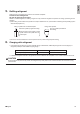


Table Of Contents
- Safety Considerations
- Accessories
- Precautions for Selecting a Location
- Precautions on Installation
- Outdoor Unit Installation Diagram
- Connections (connection port)
- How to Use Reducers
- Installation Space Requirements
- Selecting a Location for Installation ofthe Indoor Units
- Outdoor Unit Installation
- 1. Installing the outdoor unit
- 2. Drain work
- 3. Refrigerant piping
- 4. Pressure test and evacuating system
- 5. Refilling refrigerant
- 6. Charging with refrigerant
- 7. Refrigerant piping work
- 8. Flaring the pipe end
- Wiring
- Priority Room Setting
- Night Quiet Mode setting•
- COOL/ HEAT mode lock [S15]
- Pump Down Operation
- Trial Operation and Testing
- 1. Wiring error check
- 2. Trial operation and testing
- 3. Test items

15 ■English
Night Quiet Mode setting
• Ifnightquietmodeistobeused,initialsettingsmustbemadewhentheunitisinstalled.Explainnightquietmode,asdescribed
below,totheuser,andconrmwhetherornottheuserwantstousenightquietmode.
About night quiet mode
The night quiet mode function reduces operating noise of the outdoor unit at nighttime. This function is useful if the user is
worried about the effects of the operating noise on the neighbors.
However, if night quiet mode is running, cooling capacity will be saved.
Setting procedure
Turn the night quiet mode switch (SW6-1) to on.
COOL/ HEAT mode lock [S15]
• Use the S15 connector to set the unit to only cool or heat.
Setting to only heat (H) : short-circuit pins 1 and 3 of the connector [S15]
Setting to only cool (C) : short-circuit pins 3 and 5 of the connector [S15]
Thefollowingspecicationsapplytotheconnectorhousingandpins.
JST products Housing: VHR-5N
Pin: SVH-21T-1,1
NotethatforcedoperationisalsopossibleinCOOL/HEATmode.
COOL mode (C)
HEAT mode (H)
1 3 5
Service PC-board
HEAT
COOL
4
3
2
1
2
1
E
D
C
B
A
COOL
4
3
2
1
2
1
E
D
C
B
A
Screw
Remove
the switch
cover
Night quiet mode
setting switch
(SW6-1)
2
1
ON OFF
01_EN_3P500432-6E.indd 15 10/17/2019 3:02:09 PM