
3MXL24RMVJUA Installation Manual
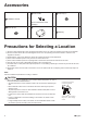
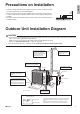
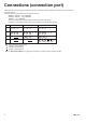
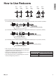
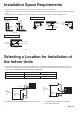
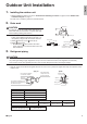
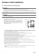
Table Of Contents
- Safety Considerations
- Accessories
- Precautions for Selecting a Location
- Precautions on Installation
- Outdoor Unit Installation Diagram
- Connections (connection port)
- How to Use Reducers
- Installation Space Requirements
- Selecting a Location for Installation ofthe Indoor Units
- Outdoor Unit Installation
- 1. Installing the outdoor unit
- 2. Drain work
- 3. Refrigerant piping
- 4. Pressure test and evacuating system
- 5. Refilling refrigerant
- 6. Charging with refrigerant
- 7. Refrigerant piping work
- 8. Flaring the pipe end
- Wiring
- Priority Room Setting
- Night Quiet Mode setting•
- COOL/ HEAT mode lock [S15]
- Pump Down Operation
- Trial Operation and Testing
- 1. Wiring error check
- 2. Trial operation and testing
- 3. Test items

5 ■English
Connections (connection port)
Install the indoor unit according to the table below, which shows the relationship between the class of indoor unit and the
corresponding port.
The total indoor unit class that can be connected to this unit:
2MXS18*, 2MXL18* – Up to 24000 Btu
3MXS24*, 3MXL24* – Up to 39000 Btu
4MXS36* – Up to 48000 Btu
Thelinesetpipingsizeisdeterminedbythesizeoftheindoorunitttings.
Reducers are used at the outdoor unit to accommodate the correct gas line pipe size.
3MXS24∗, 3MXL24∗ 4MXS36∗
Port
2MXS18∗, 2MXL18∗
B
07 , 09 , 12 , ,15 1807 , 09 , 12 , 15 07 , 09 , 12 , ,15 18
D
07 , 09 , 12 , ,15 18 , 24
A
07 , 09
,
12
07 , 09
,
12
07 , 09
,
12
C
07 , 09 , 12 , ,15 18 07 , 09 , 12 , ,15 18
: Use a reducer to connect pipes.
: Use No. 2 and 4 reducers
: Use No. 5 and 6 reducers
: Use No. 1 and 3 reducers
#
# # #
######
# # #
###
Refer to “How to Use Reducers” on page 6 for information on reducer numbers and their shapes.
01_EN_3P500432-6E.indd 5 10/17/2019 3:02:06 PM