English Français INSTALLATION MANUAL R410A Split Series Español DAIKIN ROOM AIR CONDITIONER Installation manual Manuel dinstallation Manual de instalación MODELS FVXS09NVJU FVXS12NVJU FVXS15NVJU FVXS18NVJU 00_CV_3P379970-7B.
Contents Safety Considerations .................................... 1 4. Installing indoor unit .................................................... 8 4-1. Preparation .......................................................... 8 Accessories ..................................................... 3 4-2. Installation ........................................................... 9 5. Flaring the pipe end..................................................... 12 Choosing an Installation Site .....................
• Make sure that all wiring is secured, that specified wires are used, and that no external forces act on the terminal connections or wires. Improper connections or installation may result in fire. • When wiring, position the wires so that the electrical wiring box cover can be securely fastened. Improper positioning of the electrical wiring box cover may result in electric shock, fire, or the terminals overheating. • Before touching electrical parts, turn off the unit.
Accessories A Mounting plate 1 B Titanium apatite photocatalytic air-purifying filter 2 C Drain hose 1 D Insulation tape 2 E Wireless remote controller 1 F Remote controller holder 1 G Fixing screw for remote controller holder 1/8” × 13/16” (M3 × 20mm) 2 H Indoor unit fixing screw 3/16” × 1” (M4 × 25mm) 9 J Dry battery AAA.
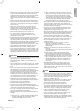
English Indoor Unit Installation Diagram • The indoor unit may be mounted in any of the 3 styles shown here. Exposed Half concealed Concealed A Mounting plate Molding Floor Installation Grid (field supply) Wall Installation • Recommended mounting plate retention spots and dimensions.
Indoor Unit Installation 1. Refrigerant piping 1) 2) 3) 4) Drill a hole (φ2-9/16 inch (65mm) in diameter) in the spot indicated by the symbol in the illustration as below. The location of the hole is different depending on which side of the pipe is taken out. For piping, refer to “6. Connecting the refrigerant pipe” on page12. Allow space around the pipe for a easier indoor unit pipe connection.
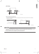
English [Back piping] 2-15/16 (75) 2-15/16 (75) Right back piping 1-3/4 (45) 1-3/4 (45) Left back piping unit: inch (mm) About the outdoor unit refrigerant pipe • In order to connect the pipe, the outdoor unit refrigerant pipe must have a length of at least 13-3/4 inch (350mm) measured from the wall. Wall 1-3/4 (45) Outdoor unit refrigerant pipe 13-3/4 (350) or more 2-15/16 (75) Floor unit: inch (mm) CAUTION Minimum allowable length • The suggested shortest pipe length is 8.2ft (2.
Indoor Unit Installation 2. Drilling a wall hole and installing wall embedded pipe WARNING For metal frame or metal board walls, be sure to use a wall embedded pipe and wall hole cover in the feed-through hole to prevent possible heat, electric shock, or fire. • Be sure to caulk the gaps around the pipes with caulking material to prevent condensation. 1) Drill a feed-through hole with a φ2-9/16 inch (65mm) diameter through the wall at a downward angle toward the outside.
English 4. Installing indoor unit 4-1. Preparation 1)Slide the stoppers. • Remove the front panel. 1) Slide until the 2 stoppers click inside. 2) Open the front panel forward and remove the string. 3) Remove the front panel. String Open the front panel 2)Remove the string. 3 tabs • Remove the front grille. 1) Remove the 4 screws. 2) Pull the front grille and remove the 3 tabs. Front grille Casing Remove front grille 4 screws • Remove the upper and the side casings. 1) Remove the 7 screws.
Indoor Unit Installation 4-2. Installation Exposed installation 1) Secure the indoor unit [Floor Installation] • Secure the indoor unit using 6 screws. (2 screws for floor and 4 screws for rear wall) Casing 4 screws H Indoor unit fixing screws 3/16” × 1” (M4 × 25mm) 2 screws H Indoor unit fixing screws 3/16” × 1” (M4 × 25mm) [Wall Installation] • Secure the A mounting plate using 5 screws. • Secure the indoor unit using 4 screws for rear wall.
English Half concealed installation 1) The size of a wall opening space shown in the illustration on the right. Open size Opening space Floor 23-1/16 – 23-7/16 (585 – 595) 26-3/8 – 27-3/16 (670-690) unit: inch (mm) 2) The rear of the unit can be fixed with screws at the points shown in the illustration as below. Be sure to install the propping object in accordance with the depth of the inner wall.
Indoor Unit Installation Concealed installation • Install the unit according to the instructions below. Failure to do so may cause lead to both cooling and heating failure and the condensation inside the house. 1) Allow enough space between the main unit and ceiling not to obstruct the flow of cool/warm air. 2) Place a partition plate between outlet and inlet sections. 3) Place a partition plate on the right side. 4) Change the upward airflow dipswitch (SW2-4) to ON to limit the upward airflow.
English 5. Flaring the pipe end 1) 2) 3) 4) 5) Cut the pipe end with a pipe cutter. Remove burrs with the cut surface facing downward, so that the filings do not enter the pipe. Put the flare nut on the pipe. Flare the pipe. Check that the flaring has been done correctly. WARNING • • • • • • Do not apply mineral oil to the flare. Prevent mineral oil from getting into the system as this would reduce the service life of the units. Never use piping which has been used for previous installations.
Indoor Unit Installation 6-1. Caution on piping handling 1) Protect the open end of the pipe against dust and moisture. 2) All pipe bends should be as gentle as possible. Use a pipe bender for bending. Wall Be sure to place a cap. Rain If no flare cap is available, cover the flare mouth with tape to keep dirt or water out. 6-2.
English 9. Wiring With a multi indoor unit , install as described in the installation manual supplied with the multi outdoor unit. • Live the sensor securing plate, remove the front electrical wiring box cover, and connect the branch wiring to the terminal block. 1) As shown in the illustration, insert the wires including the ground wire into the conduit and secure them with lock nut onto the conduit mounting plate. 2) Strip wire ends (3/4 inch (20mm)).
Indoor Unit Installation 10. When connecting to an HA system 1) 2) 3) 4) 5) 6) 7) 8) 9) 10) 11) 12) 13) 14) 15) 16) Remove the front panel and the front grille. (Refer to “4-1. Preparation” on page 8.) Open up the sensor securing plate. (See Fig. 3) Remove the front electrical wiring box cover (4 tabs). (See Fig. 3) Remove connectors 1 2 3 . (See Fig. 4 and Fig. 5) After removing the ground wires (2 screws), remove the electrical wiring box (1 screw). (See Fig. 6 ) Remove the thermistor. (See Fig.
English 11. How to set the different addresses • When 2 indoor units are installed in 1 room, the 2 wireless remote controllers can be set for different addresses. Change the address setting of one of the 2 units. When cutting the jumper be careful not to damage any of the surrounding parts. 1) Remove the electrical wiring box. (Refer to “10. When connecting to an HA system” on page 15 steps 1)-7).) 2) Cut the address jumper (JA) on the printed circuit board.
Trial Operation and Testing 1. Trial operation and testing • Trial operation should be carried out in either COOL or HEAT operation. 1-1. Measure the supply voltage and make sure that it is within the specified range. 1-2. In COOL operation, select the lowest programmable temperature; in HEAT operation, select the highest programmable temperature. 1-3.
English MEMO ■English 01_EN_3P379970-7B.
Two-dimensional bar code is a manufacturing code. 3P379970-7B 00_CV_3P379970-7B.