
FVXS Installation Manual
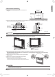
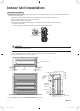

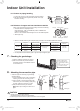
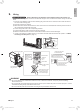
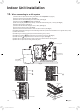
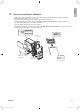
Table Of Contents

15 ■English
Indoor Unit Installation
10. When connecting to an HA system
1) Remove the front panel and the front grille. (Refer to “4-1. Preparation” on page 8.)
2) Open up the sensor securing plate. (See Fig. 3)
3) Remove the front electrical wiring box cover (4 tabs). (See Fig. 3)
4) Remove connectors
1
2
3
. (See Fig. 4 and Fig. 5)
5) After removing the ground wires (2 screws), remove the electrical wiring box (1 screw). (See Fig. 6 )
6) Remove the thermistor. (See Fig. 7)
7) Remove the side electrical wiring box cover (7 tabs). (See Fig. 3)
8) Cut off the pins using a nipper. (See Fig. 3)
9) Wire and connect the HA connection cord to the S21 connector. (See Fig. 3)
10)
Install the side electrical wiring box cover while being careful not to pinch the HA connection cord or ground wires (7 tabs).
11) Attach the thermistor.
12) Install the ground wires (2 screws) and the electrical wiring box (1 screw).
13) Install the connectors
1
2
and guide the cord as shown in the gure. (See Fig. 4)
14) Install connector
3
and guide the cord as shown in the gure. (See Fig. 5)
15) Attach the front electrical wiring box cover (4 tabs), and close the sensor securing plate.
16) Attach the front panel and the front grille as they were.
S21
Sensor securing plate
Front electrical
wiring box cover
Side electrical
wiring box cover
Cut off the pins using a nipper.
Be careful not to pinch the HA connection cord or ground wire.
Fig. 3
Connector
1
Connector
2
Connector
3
Fig. 4 Fig. 5
Screws
Ground wires
Thermistor
Fig. 6 Fig. 7
01_EN_3P379970-7B.indd 15 11/12/2015 13:30:03