
5MXS48TVJU Installation Manual
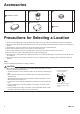
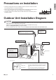
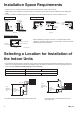
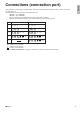
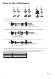
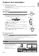
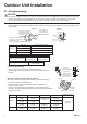
Table Of Contents
- Safety Considerations
- Accessories
- Precautions for Selecting a Location
- Precautions on Installation
- Outdoor Unit Installation Diagram
- Installation Space Requirements
- Selecting a Location for Installation ofthe Indoor Units
- Connections (connection port)
- How to Use Reducers
- Outdoor Unit Installation
- Wiring
- Priority Room Setting
- Night Quiet Mode setting
- COOL/HEAT mode lock [S15]
- Pump Down Operation
- Trial Operation and Testing

8■English
Outdoor Unit Installation
1. Installing the outdoor unit
• When installing the outdoor unit, refer to “Precautions for Selecting a Location” on page 3 and the “Outdoor Unit
Installation Diagram” on page 4.
• If drain work is necessary, follow the procedures below.
2. Drain work
CAUTION
• In cold areas, do not use a drain socket, drain plugs and a drain hose with the outdoor
unit. (Drain water may freeze, impairing heating performance.)
• Ifthedrainportiscoveredbyamountingbaseoroorsurface,placeadditionalfoot
bases of at least 3-15/16 inch (100mm) in height under the outdoor unit’s feet.
1) Insert the
D
drainplugintothebottomframeuntilitisushwiththebottomframe
around the entire circumference, as shown in area A.
Bottom frame
Drain plug insert direction
Area A
Be careful not to push in
the drain plug too far.
2)
Insert
C
drain socket cap onto
B
drain socket beyond the projection around
B
drain socket.
3) Insert
B
drain socket into the matching drain hole.
After insertion, turn it about 40° clockwise.
NOTE
Check that
C
drain socket cap is correctly engaged with the projection of
B
drain socket.
Otherwise, water leakage may result.
4) Connectthedrainhose(eldsupplied;internaldiameterof1inch(25mm))to
B
drain
socket.
(Ensuretherearenobendsinthehoseifitistoolongorhangsdown.)
5) Make sure the
D
drain plugs and the
B
drain socket of the outdoor unit are securely
inserted and there is no leakage.
Drain plugs
D
Drain plugs
Air outlet side
B
Drain
socket
D
C
Drain socket cap
B
Drain socket
Projection
Projection
3. Flaring the pipe end
WARNING
• Donotusemineraloilonaredpart.
• Prevent mineral oil from getting into the system as this would reduce the service life of the units.
• Never use piping which has been used for previous installations. Only use parts which are delivered with the unit.
• Never install a dryer to this R410A unit in order to guarantee its service life.
• The drying material may dissolve and damage the system.
• Incompletearingmaycauserefrigerantgasleakage.
CAUTION
Do not reuse joints which have been used once already.
1) Cut the pipe end with a pipe cutter.
2) Remove burrs with the cut surface facing
downward so that the chips do not enter the
pipe.
3) Putthearenutonthepipe.
4) Flare the pipe.
5) Checkthatthearingisproperlymade.
Check
Flare’s inner
surface must be
flaw-free.
The pipe end must
be evenly flared in
a perfect circle.
Make sure that the
flare nut is fitted.
Set exactly at the position shown below.
Flaring
A
Die
A
0-0.020 inch
(0-0.5mm)
Clutch-type
Flare tool for R410A
0.039-0.059 inch
(1.0-1.5mm)
Clutch-type (Rigid-type)
0.059-0.079 inch
(1.5-2.0mm)
Wing-nut type (Imperial-type)
Conventional flare tool
Cut exactly at
right angles.
Remove burrs.
English
01_EN_3P537039-1.indd 8 9/12/2018 7:37:44 PM