English INSTALLATION MANUAL Français DAIKIN ROOM AIR CONDITIONER Español R410A Split Series MODELS FTXS15LVJU FTXS18LVJU FTXS24LVJU 00_CV_3P297301-2.
English Safety Precautions • Read these Safety Precautions carefully to ensure correct installation. • This manual classifies the precautions into DANGER, WARNING and CAUTION. Be sure to follow all the precautions below: they are all important for ensuring safety. DANGER...........Indicates an imminently hazardous situation which, if not avoided, will result in death or serious injury. WARNING.........
Safety Precautions WARNING • During pump-down, stop the compressor before removing the refrigerant piping. If the compressor is still running and the stop valve is open during pump-down, air will be sucked in when the refrigerant piping is removed, causing abnormally high pressure which could lead to equipment damage or and personal injury. • During installation, attach the refrigerant piping securely before running the compressor.
How to attach the indoor unit Hook the claws of the bottom frame to the mounting plate. If the claws are difficult to hook, remove the front grille. How to remove the indoor unit Push up the marked area (at the lower part of the front grille) to release the claws. If it is difficult to release, remove the front grille.
Preparation before Installation 1. Removing and installing front panel • Removal method Hook fingers on the tabs on the left and right of the main body, and open until the panel stops. Slide the front panel sideways to disengage the rotating shaft. Then pull the front panel toward you to remove it. • Installation method Align the tabs of the front panel with the grooves, and push all the way in. Then close slowly. Push the center of the lower surface of the panel firmly to engage the tabs. 2.
English 3. How to set the different addresses When 2 indoor units are installed in one room, the 2 wireless remote controllers can be set for different addresses. 1) Remove the metal plate electrical wiring cover. (Refer to the When connecting to an HA system.) 2) Cut the address jumper (JA) on the printed circuit board. 3) Cut the address jumper (JA) in the remote controller. 4.
Refrigerant Piping Work 2. Refrigerant piping CAUTION • Use the flare nut fixed to the main unit to prevent it from cracking and deteriorating from age. • To prevent gas leakage, apply refrigeration oil only to the inner surface of the flare. (Use refrigeration oil for R410A.) • Use torque wrenches when tightening the flare nuts to prevent damage to the flare nuts and gas leakage. Align the centers of both flares and tighten the flare nuts 3 or 4 turns by hand.
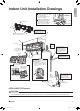
1. English Indoor Unit Installation Installing the mounting plate • The mounting plate should be installed on a wall which can support the weight of the indoor unit. 1) Temporarily secure the mounting plate to the wall, make sure that the plate is completely level, and mark the boring points on the wall. 2) Secure the mounting plate to the wall with screws.
Indoor Unit Installation 3. Laying piping, hoses, and wiring 3-1. Right-side, right-back, or right-bottom piping 1) Attach the drain hose to the underside of the refrigerant pipes with an adhesive vinyl tape. 2) Wrap the refrigerant pipes and drain hose together with insulation tape. Right-side piping Remove pipe port cover here for right-side piping. Right-back piping Right-bottom piping Remove pipe port cover here for right-bottom piping.
English 3-3. Wall embedded piping • Insert the drain hose to this depth so it won’t be pulled out of the drain pipe. Insert the drain hose to this depth so it won’t be pulled out of drain pipe. Inner wall 1-15/16” (50mm) or more Drain hose Vinyl chloride drain pipe (VP-30) Outer wall 4. Wiring With a multi indoor unit , install as described in the installation manual supplied with the Multi outdoor unit.
Indoor Unit Installation 5. Drain piping The drain hose should be inclined downward. 1) Connect the drain hose, as described right. No trap is permitted. Do not put the end of the hose in water. 2) Remove the air filters and pour some water into the drain pan to check the water flows smoothly. ϕ5/8” (ϕ16mm) 3) When drain hose requires extension, obtain an extension hose commercially available. Be sure to thermally insulate the indoor section of the extension hose.
1. English Trial Operation and Testing Trial operation and testing 1-1 Measure the supply voltage and make sure that it falls in the specified range. 1-2 Trial operation should be carried out in either cooling or heating mode. • In cooling mode, select the lowest programmable temperature; in heating mode, select the highest programmable temperature. 1) Trial operation may be disabled in either mode depending on the room temperature. Use the remote controller for trial operation as described below.
MEMO 12 01_EN_3P297301-2.
Two-dimensional bar code is a code for manufacturing. 3P297301-2 M11B120 00_CV_3P297301-2.