
Specifications
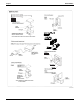


EDUS391000-C Adapter
Controls 87
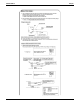
2. Control Mode Switch (RS1) Setting
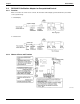
(1) For Normal Operation by Input A
Input B can be disregarded.
(2) For Instantaneous Operation by Input A and B
(Use an instantaneous input of 400 mili-sec. or more at ON time.)
(3) Do not set the switch to position 1. This switch can be set at any time.
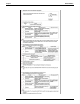
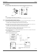
3. Fetching the Display Signal
Terminals W1 - W4 are non voltage contacts used in normal operation to output operation display (W1 and W2) and
malfunction display (W3 and W4) signals.
(The allowable current per contact is 10 mA - 3A.)
Output conditions are indicated as below.
C:1P127045
Position Input A
2
OFF ON: Unified Operation
ON OFF: Unified Stop
Position Input A Input B
3 On: Unified Operation ON: Unified Stop
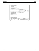
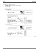
When Ry1 and Ry2 are OFF When only Ry1 is ON When only Ry2 is ON
All indoor units are stopped.
No error has occurred with the
indoor units, and at least 1 unit is
operating.
At least 1 unit has stopped operating due to malfunction, or
a communications error has occurred between the central
remote controller and the indoor unit.