
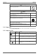
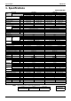
Specifications

Printed Circuit Board Connector Wiring Diagram SiBE04-624
8 Printed Circuit Board Connector Wiring Diagram
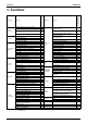
1. Printed Circuit Board Connector Wiring Diagram
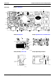
1.1 Indoor Unit
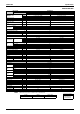
Connectors A1P (Control PCB)
A2P (Display PCB)
A3P (Signal Receiver/Transmitter PCB)
A4P (Humidity Sensor PCB)
A5P (High Voltage Unit PCB)
Note: Other designations
A1P (Control PCB)
A2P (Display PCB)
A4P (Humidity Sensor PCB)
1) S1 Connector for fan motor
2) S21 Connector for centralized control (HA)
3) S32 Connector for heat exchanger thermistor (R1T)
4) S41, S51 Connector for swing motor (horizontal, vertical)
5) S43 Connector for solenoid valve
6) S46 Connector for display PCB
7) S48 Connector for humidity sensor PCB
8) S51 Connector for reduction motor, limit switch (front panel)
9) S52 Connector for streamer unit
1) S56 Connector for control PCB
2) S57 Connector for signal receiver / transmitter PCB
3) S63 (H1P) Connector for LED PCB (multi monitor)
1) S58 Connector for display PCB
1) CN1 Connector for control PCB
1) S401 Connector for control PCB
2) S402 Connector for limit switch for streamer
3) S403 Connector for streamer
1) V1 Varistor
2) FU1 Fuse (3.15A)
3) LED A LED for service monitor (green)
4) JB
JC
Fan speed setting when compressor is OFF on thermostat
Power failure recovery function (auto-restart)
*Refer to page 300 for detail.
1) JA Address setting jumper
2) SW1 Forced operation ON / OFF switch
3) LED2 LED for timer (yellow)
4) LED3 LED for moisture operation (green)
1) R2T Room temperature thermistor