
Installation manual


Installation manual
17
E(D/B)(H/L)Q011~016AA6V3+W1
Unit for air to water heat pump system
4PW51121-1C
Wiring the 3-way valve
1 Using the appropriate cable, connect the valve control cable to
the appropriate terminals as shown on the wiring diagram.
2 Fix the cable(s) with cable ties to the cable tie mountings to
ensure strain relief.
Connection to a benefit kWh rate power supply
Electricity companies throughout the world work hard to provide
reliable electric service at competitive prices and are often authorized
to bill clients at benefit rates. E.g. time-of-use rates, seasonal rates,
Wärmepumpentarif in Germany and Austria, ... .
This equipment allows for connection to such benefit rate power
supply delivery systems.
Consult with the electricity company acting as provider at the site
where this equipment is to be installed to know whether it is
appropriate to connect the equipment in one of the benefit kWh rate
power supply delivery systems available, if any.
When the equipment is connected to such benefit kWh rate power
supply, the electricity company is allowed to:
■ interrupt power supply to the equipment for certain periods of
time;
■ demand that the equipment only consumes a limited amount of
electricity during certain periods of time.
The unit is designed to receive an input signal by which the unit
switches into forced off mode. At that moment, the outdoor unit
compressor will not operate.
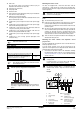
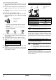
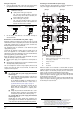
Possible types of benefit kWh rate power supply
Possible connections and requirements to connect the equipment to
such power supply are illustrated in the figure below:
When the outdoor unit is connected to a benefit kWh rate power
supply, the voltage free contact of the receiver controlling the benefit
kWh rate signal of the electricity company must be connected to
clamps 17 and 18 of X2M (as illustrated in the figure above).
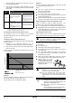
When parameter [D-01]=1 at the moment that the benefit kWh rate
signal is sent by the electricity company, that contact will open and
the unit will go in forced off mode
(1)
.
When parameter [D-01]=2 at the moment that the benefit kWh rate
signal is sent by the electricity company, that contact will close and
the unit will go in forced off mode
(2)
.
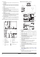
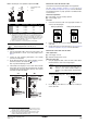
Two types of 3-way valves can be connected. Wiring
is different for each type:
■ "Spring return 2-wire" type 3-way valve
The 3-way valve should be fitted as such that
when the 3-way valve is idle (not activated), the
space heating circuit is selected.
■ "SPST 3-wire" type 3-way valve
The 3-way valve should be fitted as such that
when terminal ports 9 and 10 are electrified, the
domestic hot water circuit is selected.
"Spring return 2-wire" valve "SPST 3-wire" valve
Warnings
for a benefit kWh rate power supply like illustrated
below as type 1
■ If the benefit kWh rate power supply is of the type that
power supply is not interrupted, then control of the
heaters is still possible.
For the different possibilities of controlling heaters at
moments that benefit kWh rate is active, refer to
"[D] Benefit kWh rate power supply" on page 26.
If heaters must be controlled at moments that the
benefit kWh rate power supply is off, then these
heaters shall be connected to a separate power
supply.
■ During the period that the benefit kWh rate is active
and power supply is continuous, then stand-by power
consumption is possible (PCB, controller, pump, ...).
for a benefit kWh rate power supply like illustrated
below as types 2 or 3
Benefit kWh rate power supplies that completely shut
power supply are not allowed for this application because
of the water freeze prevention that would not be powered.
9X2M 8
10
M
9X2M 8
10
M
1 Benefit kWh rate power supply box
2 Receiver controlling the signal of the electricity company
3 Power supply to outdoor unit
4 Voltage free contact
0
Allowed
X
Not allowed
(1) When the signal is released again, the voltage free contact will close and
the unit will restart operation. It is therefore important to leave the auto
restart function enabled. Refer to "[3] Auto restart" on page 22.
(2) When the signal is released again, the voltage free contact will open and
the unit will restart operation. It is therefore important to leave the auto
restart function enabled. Refer to "[3] Auto restart" on page 22.
1
2
3
X2M17 18
X40A
A1P
LN
2
4
1
3
3
*
DHQ/
*
DLQ/
*
BHQ/
*
BLQ
LN
2
1
43
43
LN
2
1
S2S
S2S
S2S
[D-01]=1
1
2
3
LN
2
1
3
LN
2
1
43
43
LN
2
1
S2S
S2S
S2S
[D-01]=2