
Technical data

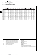

•Altherma
TM
• Monobloc
169
• Monobloc • EBHQ011-016AA6V3
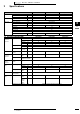
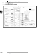
7 Wiring diagram
7 - 1 Wiring diagram
3
7
2TW58016-1
EBHQ011-016AA6V3
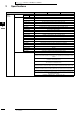
A1P Printed circuit board (Main)
A2P Printed circuit board (INV)
A3P Printed circuit board (Noise filter)
A4P Printed circuit board
BS1∼BS4 Push button switch
C1∼C4 Capacitor
DS1 DIP switch
E1H Bottomplate heater
E1HC Crankcase heater
F1U, F3U, F4U Fuse (T 6.3A/250V)
F6U Fuse (T 5.0A/250V)
F7U, F8U Fuse (F 1,0A/250V)
H1P∼7P (A2P) Light Emit. Diode (Serv. Monitor-Orange)
Prepare, Test --------- Flickering
Malfunction Detection -- Light up
HAP (A1P) Light emitting diode (service monitor green)
K1R Magnetic relay (Y1S)
K4R Magnetic relay (E1HC)
K10R Magnetic relay
K11R Magnetic relay
L1R Reactor
M1C Motor (Compressor)
M1F Motor (Fan) (upper)
M2F Motor (Fan) (lower)
PS Switching power supply
Q1DI Field earth leakage breaker (300mA)
R1 Resistor
R2 Resistor
R1T Thermistor (Air)
R2T Thermistor (Discharge)
R3T Thermistor (Suction)
R4T Thermistor (Heat exchanger)
R5T Thermistor (heat exchanger middle)
R6T Thermistor (Liquid)
RC Signal receiver circuit
R10T Thermistor (Fin)
S1NPH Pressure sensor
S1PH Pressure switch (High)
TC Signal transmission circuit
V1R Power module
V2R, V3R Diode module
V1T IGBT
X1M Terminal strip (Power supply)
Y1E Electronic expansion valve
Y1S Solenoid valve (4 way valve)
Z1C∼Z3C Noise filter (ferrity core)
Z1F∼Z4F Noise filter
Optional connector
X1Y Connector
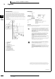
Notes:
1 This wiring diagram only applies to the compressor module switchbox
2 L: Live N:Neutral g: Field wiring
3 D : Terminal strip F : Connector T : Connection R : Protective earth (screw)
: Connector p : Noiseless earth G : Terminal
4 NOT APPLICABLE
5-
6 Do not operate the unit by short-circuiting protection device S1PH
7 Colors: BLK: black, RED: red, BLU: blue, WHT: white, YLW: yellow, ORG: orange, BRN: brown, GRN: green
8 Confirm the method of setting the selector switches (DS1) by service manual.Factory setting of all switches: ’’OFF’’.
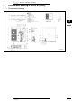
Power supply
N-50Hz
230V
Only for E(D/B)LO*
Compressor module switchbox
Position of
compressor
terminal
Wire entrance
El. comp. Assy
(Position of elements)
Option
Wiring dependent on
model
To hydromodule switchbox (8.5 Page 2
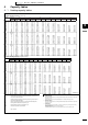
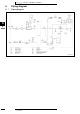
2TW58016-1
EBHQ011-016AA6V3
Outdoor unit
Power supply
230V 1N∼50Hz
>> See note 2 <<
User
interface
Only forEKHWS*V3
Option
Example field
supply
thermostat
Option
Field wiring
Wiring dependent on
model
Wire colour
See note 7
For *KHWSU*V3 Option
NO valve
NC valve
heating
cooling
230V AC
supply from
PCB
Only for EKHW
Option
Only for *KHW Option
Only
for EKSOLHWAV1Option
Domestic hot water
tank
Electric heater fuse
F1B 32A
*KHW kit fuse
F2B 20A
Domestic hot water
tank
See note 7
For *KHWSU*V3 Option
Solar pump connection
Only for EKRP1HB &
EKSOLHWAV1
Option
Alarm output
Cooling/heating
on/off output
Solar input
3wiretype(SPST)
Only for EKSOLHWAV1
Option
See note 9
Field wiring
PCB
See note 8
Only
for *KHWE*Option
Domestic hot water
tank
Only for *KHWE*V3
Option
Only
for *KHW(S/E)*Option
Only
for EKRTETS* Option
Only
for *KHW(S/E)* Option
Only
for *KRTR* Option
Only
for *KRTW* Option
Only for EC/BLQOption
Notes:
1 This wiring diagram only applies to the compressor module
2 Use one and same dedicated power supply compressor module switchbox, hydromodule switchbox and *KHW* option
3
:Field wiring No/Nc normal open/normal closed SPST - single pole single throw.
4
:Terminal strip :Connector :Terminal :Protective earth
5
Do not operate the unit by short-circuiting any protection device.
6
BLK: Black / WHT: White / RED: Red / BLU: Blue / PINK: Pink / YLW: Yellow
BRN: Brown / GRY: Grey / GRN: Green / ORG: Orange / VIO: Violet
7 For *KHWSU*V3, refer to option manual
8 Option PCB works with an external 230V AC power supply unit. (N,L)
9 For EKSOLHWAV1, refer to option manual
10 Backupheater kW reduction, refer to installation manual
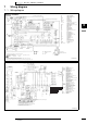
From compressor
module switchbox
(B.7 PageA)
Standard 6kw
(_)
See note 10
Reduced 3kw
See note 10
A11P : Main PCB
A12P : User interface PCB
A3P (*KRTW) : Thermostat (PC=power circuit)
A4P (EKRTR) : Solar/remote alarm PCB
A4P (*KRTR) : Receiver PCB
E11H-E12H-E13H
: Backup heater element 1-2-3 (6 kW)
E4H : Booster heater (3kW)
E5H : Switchbox heater
E6H : Expansion vessel heater
F1B : Fuse backup heater
F1T : Thermal fuse backup heater
F2B : Fuse booster heater
F8U, F9U : Fuse 1,0A F 250V
FU1 : Fuse 3,15A T 250V for PCB
FU2 : Fuse 5A T 250V
FuS, FuR : Fuse 5A 250V for solar/remote alarm PCB
K1M : Contactor backup heater step
K3M : Contactor booster heater
K4M : pump relay
K5M : Contactor for backup heater all-pole disconnection
K7M : Relay for solar pump
M1P : Pump
M2S : 2 way valve for cooling mode
M3S : 3 way valve: floorheating/domestic hot water
PHC1 : Optocoupler input circuit
Q1DI : Earth leakage protector
Q1L : Thermal protector backup heater
Q2L : Thermal protector1/2Booster heater
R1H (*KRTR) : Humidity sensor
R1T (*KRTW/R) : Ambient sensor
R2T (EKRTETS) : External sensor (floor or ambient)
R11T : Outlet water heat-exchanger thermistor
R12T : Outlet water backup heater thermistor
R13T : Refrigerant liquid side thermistor
R14T : Inlet water thermistor
R5T (*KHW*) : Domestic hot water thermistor
S1L : Flowswitch
S1S : Solar pumpstation relay
S2S : benefit kWh rate power supply contact
SS1 : DIP switch
S1T : thermostat switchbox heater
S2T : thermostat expansion vessel heater
TR1 : Transformer 24V for PCB
V1S, V2S : Spark suppression 1, 2
X1M-X10M : Terminal strips
X2Y : Connector