OPERATION MANUAL Unit for air to water heat pump system EDHQ011BA6V3 EDHQ014BA6V3 EDHQ016BA6V3 EDHQ011BA6W1 EDHQ014BA6W1 EDHQ016BA6W1 EDLQ011BA6V3 EDLQ014BA6V3 EDLQ016BA6V3 EDLQ011BA6W1 EDLQ014BA6W1 EDLQ016BA6W1 EBHQ011BA6V3 EBHQ014BA6V3 EBHQ016BA6V3 EBHQ011BA6W1 EBHQ014BA6W1 EBHQ016BA6W1 EBLQ011BA6V3 EBLQ014BA6V3 EBLQ016BA6V3 EBLQ011BA6W1 EBLQ014BA6W1 EBLQ016BA6W1
EDHQ011~016BA6V3 EDLQ011~016BA6V3 EBHQ011~016BA6V3 EBLQ011~016BA6V3 CONTENTS EDHQ011~016BA6W1 EDLQ011~016BA6W1 EBHQ011~016BA6W1 EBLQ011~016BA6W1 Operation manual Unit for air to water heat pump system Page INTRODUCTION Introduction ..................................................................................... 1 This manual....................................................................................... 1 This unit...........................................................................
Safety considerations The precautions listed here are divided into the following four types. They all cover very important topics, so be sure to follow them carefully. OPERATING THE UNIT INTRODUCTION Meanings of DANGER, WARNING, CAUTION and NOTE symbols. DANGER The heat pump system is designed to provide you a comfortable indoor climate for many years at low energy consumption. Indicates an imminently hazardous situation which, if not avoided, will result in death or serious injury.
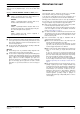
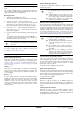
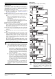
OPERATING THE DIGITAL CONTROLLER Name and function of buttons and icons Operating the unit comes down to operating the digital controller. 8 5 6 24 15 18 3 16 2 17 1 Never let the digital controller get wet. This may cause an electric shock or fire. Never press the buttons of the digital controller with a hard, pointed object. This may damage the digital controller. Never inspect or service the digital controller yourself, ask a qualified service person to do this.
6. CLOCK DISPLAY 8 The clock display shows the current time. When reading or programming the schedule timer, the clock display shows the action time. 7. SCHEDULE TIMER ICON p This icon indicates that the schedule timer is enabled. 8. 9. 25. SPACE HEATING/COOLING BUTTON = This button allows manual switching between cooling or heating mode (provided the unit is not a heating only unit). When the unit is connected with an external room thermostat, this button is not operable and the icon e is shown. 26.
Setting up the controller After initial installation, the user can set the clock and day of the week. The controller is equipped with a schedule timer that enables the user to schedule operations. Setting the clock and day of the week is required to be able to use the schedule timer. Space cooling operation (c) In this mode, cooling will be activated as required by the water temperature set point.
Controller operations Selection and setting of domestic water heating (w) 1 Use the v button to activate domestic water heating ( w). Icon w appears on the display. 2 Use the wi or wj button to display the actual temperature set point and subsequently, to set the correct temperature. Manual operation In manual operation, the user manually controls the settings of the installation.
Schedule timer operation What can the schedule timer do? In schedule timer operation, the installation is controlled by the schedule timer. The actions programmed in the schedule timer will be executed automatically. The schedule timer allows the programming of: 1. The schedule timer always follows the last command until a new command is given. This means that the user can temporarily overrule the last executed programmed command by manual operation (Refer to "Manual operation" on page 6).
Programming and consulting the schedule timer Programming Programming space cooling or space heating Getting started Programming the schedule timer is flexible (you can add, remove or alter programmed actions whenever required) and straightforward (programming steps are limited to a minimum). However, before programming the schedule timer, remind: ■ Familiarise yourself with the icons and the buttons. You will need them when programming. Refer to "Name and function of buttons and icons" on page 3.
Programming space cooling or space heating is carried out as follows: NOTE Programming quiet mode, booster heating or domestic water heating Returning to previous steps in the programming procedure without saving modified settings is done by pressing the pr button. 1 Use the = button to select the operation mode (cooling or heating) you want to program. 2 Press the < button. The actual mode is blinking. 3 Press the < button to confirm the selected mode. The actual day is blinking.
10 Press the < button for 5 seconds to store the programmed actions. If the < button is pressed when action number 3 is displayed, actions 1, 2 and 3 are stored but 4 and 5 are deleted. You automatically return to step 4. By pressing the pr button several times, you return to previous steps in this procedure and finally return to normal operation. Tips and tricks Programming the next day(s) After confirming the programmed actions of a specific day (i.e.
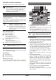
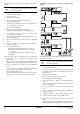
FIELD 1 Press the z button for a minimum of 5 seconds to enter FIELD SET MODE. The $ icon (3) will be displayed. The current selected field setting code is indicated ; (2), with the set value displayed to the right - (1). 2 Press the bgi button to select the appropriate field setting first code. 3 Press the bgj button to select the appropriate field setting second code. The field settings [2] depends on the relevant local laws and regulations.
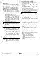
[1] Weather dependent set point (heating operation only) [2] Disinfection function The weather dependent set point field settings define the parameters for the weather dependent operation of the unit. When weather dependent operation is active the water temperature is determined automatically depending on the outdoor temperature: colder outdoor temperatures will result in warmer water and vice versa.
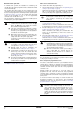
[4] Space heating off temperature [D] Local shift value weather dependent Space heating off temperature Local shift value weather dependent ■ [4-02] Space heating off temperature: outdoor temperature above which space heating is turned off, to avoid overheating. [9] Cooling and heating set points The purpose of this field setting is to prevent the user from selecting a wrong (i.e., too hot or too cold) leaving water temperature.
Field settings table First code 0 Second code 2 3 5 6 7 8 9 Value Date Value Default value Range Step Unit User permission level 3 2/3 1 — Weather dependent set point 00 Low ambient temperature (Lo_A) –10 –20~5 1 °C 01 High ambient temperature (Hi_A) 15 10~20 1 °C 02 Set point at low ambient temperature (Lo_TI) 40 25~55 1 °C 03 Set point at high ambient temperature (Hi_TI) 25 25~55 1 °C Fri Mon~Sun, All — — Disinfection function 00 Operation interval 01
First code A b C D E F Second code Installer setting at variance with default value Setting name Value Date Value Default value Range Step Unit Quiet mode 00 Quiet mode type 0 0/2 — — 01 Parameter 01 3 — — — 02 Not applicable 1 Read only — — 03 Not applicable 0 Read only — — 04 Not applicable 0 Read only — — Not applicable 00 Not applicable 0 Read only — — 01 Not applicable 0 Read only — — 02 Not applicable 0 Read only — — 03 Not applicable 0
MAINTENANCE Important information regarding the refrigerant used This product contains fluorinated greenhouse gases covered by the Kyoto Protocol. Refrigerant type: R410A GWP(1) value: 1975 (1) GWP = global warming potential Periodical inspections for refrigerant leaks may be required depending on European or local legislation. Please contact your local dealer for more information. Standstill During longer periods of standstill, e.g.
NOTES
4PW57622-1 Copyright © Daikin