INSTALLATION MANUAL Indoor unit for air to water heat pump system EKHBH016AB EKHBX016AB
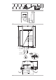
1 1 2 1x 3 1x 4 1x 5 2x 6 1x 7 1x 1 2 300 500 ≥ ≥350 2 922 668 35 895 3 235 1 235 1-1/4" FBSP 30° 1-1/4" MBSP 96 39 48 361 90 ° 35 2 3 48 142 101 502 3 4 5 8 2x 2x
CE - DECLARACION-DE-CONFORMIDAD CE - DICHIARAZIONE-DI-CONFORMITA CE - ¢H§ø™H ™YMMOPºø™H™ CE - ERKLÆRING OM-SAMSVAR CE - ILMOITUS-YHDENMUKAISUUDESTA CE - PROHLÁŠENÍ-O-SHODĚ 05 Nota * 04 Bemerk * 03 Remarque * 02 Hinweis * 01 Note * 19 ob upoštevanju določb: 20 vastavalt nõuetele: 21 следвайки клаузите на: 22 laikantis nuostatų, pateikiamų: 23 ievērojot prasības, kas noteiktas: 24 održiavajúc ustanovenia: 25 bunun koşullarına uygun olarak: delineato nel e giudicato positivamente da secondo il
EKHBH016AB*** EKHBX016AB*** CONTENTS Installation manual Indoor unit for air to water heat pump system Page READ THESE INSTRUCTIONS CAREFULLY BEFORE INSTALLATION. KEEP THIS MANUAL IN A HANDY PLACE FOR FUTURE REFERENCE. Introduction ....................................................................................... 1 General information.................................................................................... 1 Scope of this manual..........................................................
Model identification PH Indoor unit 3 EK 1 HB X 016 AB 3 V3 Backup heater nominal voltage: (optional) V3 = 1P, 230 V WN = 3P, 400 V T1 = 3P, 230 V 2 4 1 Heat pump capacity 2 Required heating capacity (site dependent) 3 Additional heating capacity provided by the backup heater 4 Equilibriumtemperature (can be set through the user interface, refer to "Field settings" on page 16) TA Ambient (outdoor) temperature PH Heating capacity Backup heater capacity (kW) (optional) TA Domestic
TYPICAL APPLICATION EXAMPLES Application 2 When the AD system is used in series with another heat source (e.g. gas boiler), it shall be made sure that the return water temperature to the heat exchanger does not exceed 55°C. Daikin shall not be held liable for any damage resulting from not observing this rule. Space heating only application without room thermostat connected to the indoor unit. The temperature in each room is controlled by a valve on each water circuit.
Domestic water heating Pump operation and space heating and cooling When domestic water heating mode is enabled (either manually by the user, or automatically through a schedule timer) the target domestic hot water temperature will be achieved by a combination of the heat exchanger coil and the electrical booster heater. According to the season, the customer will select cooling or heating on the room thermostat (T). This selection is not possible by operating the user interface.
1 Outdoor unit 2 Indoor unit 3 Heat exchanger 4 Pump 5 Shut-off valve 6 Collector (field supply) 7 Shut-off valve 9 By-pass valve (field supply) 13 Motorised 2-way valve to shut off the floor heating loops during cooling operation (field supply) 14 Motorised 2-way valve for activation of the room thermostat (field supply) FCU1..3 Fan coil unit with thermostat (field supply) FHL1..3 Floor heating loop (field supply) T Heating only room thermostat (field supply) T4..
1 Air purge valve Remaining air in the water circuit will be automatically removed via the air purge valve. 2 Backup heater The backup heater consists of an electrical heating element that will provide additional heating capacity to the water circuit if the heating capacity of the outdoor unit is insufficient due to low outdoor temperatures. 3 Temperature sensors Four temperature sensors determine the water and refrigerant temperature at various points in the water circuit.
11 Switch box main components X13A socket The X13A socket receives the K3M connector (only for installations with domestic hot water tank). 12 X9A socket The X9A socket receives the thermistor connector (only for installations with domestic hot water tank).
INSTALLATION OF THE INDOOR UNIT Inspecting, handling and unpacking the unit Selecting an installation location ■ The indoor unit is packed in a cardboard box, fixed by straps on a wooden pallet. The unit is to be wall mounted in an indoor location that meets the following requirements: ■ At delivery, the unit must be checked and any damage must be reported immediately to the carrier claims agent. ■ The installation location is frost-free. ■ ■ The space around the unit is adequate for servicing.
Mounting the indoor unit Installation of the EKHBDP drain pan kit (only for EKHBX models) The weight of the indoor unit is approximately 55 kg. Two persons are required to mount the unit. 1 Fix the wall mounting bracket to the wall using appropriate plugs and screws. Make sure the wall mounting bracket is completely level. When the unit is not installed level, air might get trapped in the water circuit resulting in malfunctioning of the unit.
Checking the water volume and expansion vessel prepressure The unit is equipped with an expansion vessel of 10 litre which has a default pre-pressure of 1 bar. To assure proper operation of the unit, the pre-pressure of the expansion vessel might need to be adjusted and the minimum and maximum water volume must be checked. 1 Check that the total water volume in the installation is 20 l minimum. Example 1 The indoor unit is installed 5 m below the highest point in the water circuit.
Charging water 1 Connect the water supply to a drain and fill valve (see "Main components" on page 6). 2 Make sure the automatic air purge valve is open (at least 2 turns). 3 Fill with water until the manometer indicates a pressure of approximately 2.0 bar. Remove air in the circuit as much as possible using the air purge valves. Air present in the water circuit might cause malfunctioning of the optional backup heater.
Internal wiring - Parts table Refer to the internal wiring diagram supplied with the unit (on the inside of the indoor unit switch box cover). The abbreviations used are listed below. A1P ..................Main PCB A2P ..................Remote controller PCB (user interface) A3P ..................Thermostat (field supply, PC= internal Power Circuit) A4P .......... *......Solar/remote alarm address card E1H.......... *......Backup heater element 1 E2H.......... *......Backup heater element 2 E3H.......... *.
Procedure Connection of the valve control cables 1 Valve requirements Using the appropriate cable, connect the power circuit to the main circuit breaker as shown on the wiring diagram and the illustration below. 2 Connect the earth conductor (yellow/green) to the earthing screw on the X1M terminal. 3 Fix the cable with cable ties to the cable tie mountings to ensure strain relief.
START-UP AND CONFIGURATION The indoor unit should be configured by the installer to match the installation environment (outdoor climate, installed options, etc.) and user expertise. It is important that all information in this chapter is read sequentially by the installer and that the system is configured as applicable. DIP switch settings overview The following table summarizes the required configuration and thermostat wiring at the terminal block in the switch box.
2 ■ When no domestic hot water tank is installed, toggle switch SS2-2 should be set to OFF (default). OFF ON ■ When a domestic hot water tank is installed, toggle switch SS2-2 should be set to ON. OFF ON Domestic hot water tank installation configuration 1 2 Check that the fuses or the locally installed protection devices are of the size and type specified in the chapter "Technical specifications" on page 25. Make sure that neither a fuse nor a protection device has been bypassed.
Setting the pump speed 1 Press the z button for a minimum of 5 seconds to enter FIELD SET MODE. The $ icon (3) will be displayed. The current selected field setting code is indicated ; (2), with the set value displayed to the right - (1). 2 Press the bgi button to select the appropriate field setting first code. 3 Press the bgj button to select the appropriate field setting second code. 4 Press the pfi button and pfj button to change the set value of the select field setting.
■ [1-02] Set point at low ambient temperature (Lo_Ti): the target outgoing water temperature when the outdoor temperature equals or drops below the low ambient temperature (Lo_A). Note that the Lo_Ti value should be higher than Hi_Ti, as for colder outdoor temperatures (i.e. Lo_A) warmer water is required. ■ [1-03] Set point at high ambient temperature (Hi_Ti): the target outgoing water temperature when the outdoor temperature equals or rises above the high ambient temperature (Hi_A).
■ [5-03] Space heating priority temperature: outdoor temperature below which the domestic water will be heated by the booster heater only, i.e. low outdoor temperature. [7] Domestic hot water step length ■ [5-04] Set point correction for domestic hot water temperature: set point correction for the desired domestic hot water temperature, to be applied at low outdoor temperature when space heating priority is enabled.
[8] Domestic water heating mode timer NOTE Applies only to installations with a domestic hot water tank. The 'domestic water heating mode timer' field settings defines the minimum and maximum domestic water heating times, and minimum time between two domestic water heating cycli. ■ [8-00] Minimum running time: specifies the minimum time period during which domestic water heating should be activated, even when the target domestic water temperature has already been reached.
Field settings table Installer setting at variance with default value First code 0 Second code 2 3 5 6 7 9 C Value Default value Range Step Unit User permission level 3 2~3 1 — Low ambient temperature (Lo_A) –10 –20~5 1 °C 01 High ambient temperature (Hi_A) 15 10~20 1 °C 02 Set point at low ambient temperature (Lo_TI) 40 25~55 1 °C 03 Set point at high ambient temperature (Hi_TI) 25 25~55 1 °C Fri Mon~Sun, All — — Disinfection function 00 Operation interval 0
TEST RUN AND FINAL CHECK The installer is obliged to verify correct operation of the indoor and outdoor unit after installation. Automatic test run When the unit is put into operation (by pressing the y button) for the first time, the system will automatically perform a test run in cooling mode. The test run will take up to 3 minutes, during which no specific indication is given on the user interface.
TROUBLESHOOTING Symptom 2: The unit is turned on but the compressor is not starting (space heating or domestic water heating) This section provides useful information for diagnosing and correcting certain troubles which may occur in the unit. POSSIBLE CAUSES The unit must start up out of its operation range (the water temperature is too low). General guidelines When carrying out an inspection on the switch box of the unit, always make sure that the main switch of the unit is switched off.
Symptom 7: Space heating capacity shortage at low outdoor temperatures POSSIBLE CAUSES Backup heater operation is not activated. CORRECTIVE ACTION Check that the "backup heater operation status" field setting [4-00] is turned on, see "Field settings" on page 16. Check whether or not the thermal protector of the backup heater has been activated (refer to Main components, "Backup heater thermal protector" on page 6 for location of the reset button).
Error code Failure cause Corrective action Error code Failure cause Corrective action Booster heater thermal protector is open (applies only to installations with a domestic hot water tank) Reset the thermal protector P1 PCB failure Contact your local dealer. P4 Electric component failure Contact your local dealer. PJ Failure of capacity setting Contact your local dealer.
TECHNICAL SPECIFICATIONS General Heating/cooling models (EKHBX) Heating only models (EKHBH) Nominal capacity Refer to the Technical Data Refer to the Technical Data • cooling • heating Dimensions H x W x D Weight • machine weight • operation weight 922 x 502 x 361 922 x 502 x 361 55 kg 70 kg 55 kg 70 kg 1-1/4" MBSP(a) hose nipple Ø9.5 mm (3/8 inch) Ø15.9 mm (5/8 inch) 1-1/4" MBSP(a) hose nipple Ø9.5 mm (3/8 inch) Ø15.9 mm (5/8 inch) 10 l 3 bar 10 l 3 bar water cooled 2 28 dBA 5.
NOTES
4PW42457-1 Copyright © Daikin