INSTALLATION MANUAL Split System air conditioners FBQ35C7VEB FBQ50C7VEB FBQ60C7VEB FBQ71C7VEB FBQ100C7VEB FBQ125C7VEB FBQ140C7VEB
5 2 1 76 5 1 3 4 A 1 B ≥300 2 4 3 2 1 1 2 3 4 5 2 3 3 4 1 4 6a 6c <45 23 2 630 700 5 6b 1 3 4 4 1 23 200 4 680 6 5 1 23 680 4 680 7 6a 6b 6c 7a 180 1 160 (160~300) 425 7c 1 2 3 5 4 460 A 7a 2 7b ≥350 180 1 2 3 4 460 A 7b 8 1 9 6 7c 2 1 1 5 3 2 4 9 10 1 2 5 4 1~1.
CE - DECLARACION-DE-CONFORMIDAD CE - DICHIARAZIONE-DI-CONFORMITA CE - ¢H§ø™H ™YMMOPºø™H™ CE - ERKLÆRING OM-SAMSVAR CE - ILMOITUS-YHDENMUKAISUUDESTA CE - PROHLÁŠENÍ-O-SHODĚ 05 Nota * 04 Bemerk * 03 Remarque * 02 Hinweis * 01 Note * 19 ob upoštevanju določb: 20 vastavalt nõuetele: 21 следвайки клаузите на: 22 laikantis nuostatų, pateikiamų: 23 ievērojot prasības, kas noteiktas: 24 održiavajúc ustanovenia: 25 bunun koşullarına uygun olarak: delineato nel e giudicato positivamente da secondo il
FBQ35C7VEB FBQ50C7VEB FBQ60C7VEB FBQ71C7VEB FBQ100C7VEB FBQ125C7VEB FBQ140C7VEB CONTENTS Installation manual Split System air conditioners Page Before installation.............................................................................. 1 Precautions ■ Do not install or operate the unit in rooms mentioned below. • Places with mineral oil, or filled with oil vapour or spray like in kitchens. (Plastic parts may deteriorate.) • Where corrosive gas like sulphurous gas exists.
For the following items, take special care during construction and check after installation is finished 2. Ensure that a protective guard is installed on air suction and air outlet side to prevent that the fan blades or heat exchanger be touched. The protection must comply with relevant European and national regulations. 3. Use suspension bolts for installation. Check whether the ceiling is strong enough to support the weight of the indoor unit.
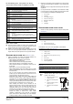
NOTE When installing an air inlet duct, select fixing screws that shall stick out maximum 5 mm at the inside of the flange to protect the air filter from damage during maintenance of the filter. 1 Air inlet duct 2 Inside of the flange 3 Fixing screw 1 2 INDOOR When installing optional accessories (except for the air inlet panel), read also the installation manual of the optional accessories.
■ Refer to Table 1 for the dimensions of flare nut spaces and the appropriate tightening torque. (Overtightening may damage the flare and cause leaks.) Table 1 Pipe gauge Tightening torque (N•m) Flare dimension A (mm) Ø6.4 15~17 8.7~9.1 Ø9.5 33~39 12.8~13.2 Ø12.7 50~60 16.2~16.6 Ø15.9 63~75 19.3~19.7 Cautions for brazing ■ Be sure to carry out a nitrogen blow when brazing.
■ Insulate the complete drain piping inside the building (field supply). If the drain hose cannot be sufficiently set on a slope, fit the hose with drain raising piping (field supply). Caution for drain socket Do not remove the drain pipe plug. Water might leak out. The drain outlet is only used to discharge water if the drain pump is not used or before maintenance. Gently put in and out the drain plug. Excessive force may deform the drain socket of the drain pan.
ELECTRIC WIRING WIRING WORK EXAMPLE AND HOW TO SET THE REMOTE CONTROLLER General instructions ■ All field supplied parts and materials and electric works must conform to local codes. ■ Use copper wire only. ■ Follow the "Wiring diagram" attached to the unit body to wire the outdoor unit, indoor units and the remote controller. For details on hooking up the remote controller, refer to the "Installation manual of the remote controller".
6. Use only specified wires and tightly connect wires to the terminals. Be careful that wires do not place external stress on the terminals. Keep wiring in neat order so that they do not obstruct other equipment such as popping open the switch box cover. Make sure the cover closes tight. Incomplete connections could result in overheating, and in the worse case, electric shock or fire.
5 When the air conditioning unit has stopped, check on an indoor unit if the second code No. of mode No. 21 is set to "02". If the air conditioning unit does not stop operating or the second code No. is not "02", repeat step 4. If the outdoor unit is not turned on, the display on the remote controller will show "U4" or "UH" (refer to "Test operation" on page 8). However, you can continue setting this function because these messages are only applicable to outdoor units.
WIRING DIAGRAM : FIELD WIRING : CONNECTOR : WIRE CLAMP : PROTECTIVE EARTH (SCREW) : LIVE : NEUTRAL L N BLK BLU BRN GRN GRY : BLACK : BLUE : BROWN : GREEN : GREY ORG PNK RED WHT YLW : ORANGE : PINK : RED : WHITE : YELLOW A1P ..................... PRINTED CIRCUIT BOARD R3T......................THERMISTOR (GAS) A2P ..................... PRINTED CIRCUIT BOARD (FAN) R5T......................THERMISTOR NTC (CURRENT LIMITING) A3P .....................
12 13 5 13 14 10 5 4 1 3 2 13 14 15 1 1 2 1 2 3 L N 2 3 11 9 8 6 7 12 2 3 4 6 1 3 4 1 2 3 L N 1 2 3 L N 1 2 3 1 2 3 12 L N P1 P2 P1 P2 5 5 P1 P2 P1 P2 6 6 14 1 16 15 1 17 2 2 3 4 4 1 2 3 L N 1 2 3 L N 1 2 3 L N 1 2 3 L N 1 2 3 1 2 3 1 2 3 1 2 3 P1 P2 P1 P2 5 5 P1 P2 16 2 3 4 4 1 2 3 3 6 1 5 P1 P2 P1 P2 6 6 17 P1 P2 P1 P2 5
4PW46842-1B Copyright © Daikin