
Specifications


EDUS281120_a Installation of indoor unit
RZR-P, RZQ-P(9) 119
3P161684-6K
6 English
Points for explanation about operations
4. NOTE TO THE INSTALLER
Be sure to instruct customers how to properly operate the unit (especially cleaning filters, operating different func-
tions, and adjusting the temperature) by having them carry out operations themselves while looking at the manual.
3. SELECTING INSTALLATION SITE
〈Hold the unit by the 4 lifting lugs when opening the box and moving it, and do not exert pressure on to any
other part piping (refrigerant, drain, etc.) or plastic parts.
If the temperature or humidity inside the ceiling might rise above 86°F or RH 80%, respectively, use the high-
humidity kit (sold separately) or add extra insulation to the main unit body.
Use glass wool or polyethylene foam as insulation and make sure it is at least 3/8in. thick and fits inside the
ceiling opening.〉
The direction this product blows can be selected. However, a separately sold shut-off material kit is
needed in order to make the unit blow in two, three, or four (corner shut-off) directions.
(1) Select an installation location with the customer’s approval which matches the following conditions.
• A location from which cool (warm) air will reach the whole room.
• A location with no objects blocking the air passage.
• A location where drainage can be done with no problem.
• A location strong enough to support the weight of the indoor unit.
• Locations where the wall is not significantly tilted.
• A location which leaves enough room for installation and service work.
• A location where there is no risk of flammable gas leaking.
• A location where the length of the indoor-outdoor piping is no longer than the tolerated length (see the
installation manual that came with the outdoor unit for details).
The items with WARNING and CAUTION marks in the operation manual are the items per-
taining to possibilities for bodily injury and material damage in addition to the general usage of
the product. Accordingly, it is necessary that you make a full explanation about the described con-
tents and also ask your customers to read the operation manual.
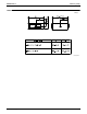
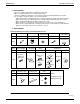
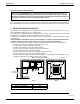
Model H (in.)
FCQ18 · 24 · 30PAVJU 10
FCQ36 · 42PAVJU 11-3/4
Fig. 2
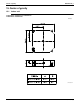
[Space required for installation] (Unit: in.)
*≥60
*≥60
*≥60
*≥60
H
Floor surface
At least 70in.
from the floor.
Air
inlet
Fig. 1
≥
60
≥
60
Air
discharge
Air
discharge