
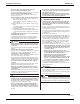
Specifications

EDUS281120_a Installation of indoor unit
RZR-P, RZQ-P(9) 149
C: 3PN06240-12Q
12 English
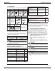
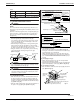
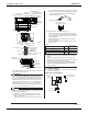
1. When using 1 remote controller for 1 indoor unit.
(Normal operation)
L1 L2
IN/D OUT/D
F
1 F2 F1 F2
Control box
L
1
L
2
P
1
P
2
P
1
P
2
F
1
F
2
T
1
T
2
Outdoor unit
Indoor unit
Power supply
208-230V
60Hz
Remote controller
2. When using 2 remote controllers for 1 indoor unit.
IN/D OUT/D
F
1 F2 F1 F2
Control box
P
1
P
2
F
1
F
2
T
1
T
2
P
1
P
2
P
1
P
2
Outdoor unit
For use with 2 remote controllers
Power supply
208-230V
60Hz
L1 L2
Indoor unit
L
1
L
2
NOTE
1. All transmission wires except for remote controller wire are
polarized and must match the terminal symbol.
2. A single switch can be used to supply power to units on the
same system. However, branch switches and branch circuit
breakers must be selected carefully.
3. Do not ground the equipment on gas pipes, water pipes or
lightning rods, or crossground with telephones. Improper
grounding could result in electric shock.
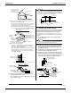
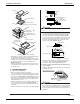
ATTACHING THE SUCTION GRILLE, 10.
THE DECORATION PANELS AND THE
PROTECTION NET
Once wiring is complete, fi rmly attach the control box lid, the
suction grille, the decoration panels and the protection net in the
order opposite to detachment.
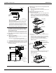
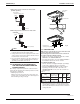
Attaching the protection net •
Attach the protection net from the way of the hook (i), fi x 2
securing screws of the middle of the other side fi rst (ii), then
fi x the remaining securing screws (iii).
Decoration
panel
Protection net
(ii)
(ii)
(i)
(i)
Hook
Hook
(ii)
Fig. 29
Protection net
securing screws (M4)
(iii)
FIELD SETTING11.
Make sure the control box lids are closed on the indoor and
outdoor units, and turn on the power.
Field setting must be made from the remote controller in
accordance with the installation manual.
Setting can be made by changing the “Mode No.”, “FIRST •
CODE NO.”, and “SECOND CODE NO.”.
For setting and operation, refer to the “FIELD SETTING” in •
the installation manual of the remote controller.
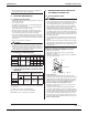
Setting air fi lter sign11-1
Remote controllers are equipped with liquid crystal display •
air filer signs to display the time to clean air filters.
Change the SECOND CODE NO. according to “Table 5” •
depending on the amount of dirt or dust in the room.
(SECOND CODE NO. is factory set to “01” for air fi lter con-
tamination-light.)
Table 5
Setting
Spacing time of
display air fi lter sign
(long life type)
Mode
No.
FIRST
CODE
NO.
SECOND
CODE
NO.
Air fi lter contamina-
tion-light
Approx. 2500 hrs
10 (20) 0
01
Air fi lter contamina-
tion-heavy
Approx. 1250 hrs 02
<When using wireless remote controllers>
When using wireless remote controllers, wireless remote •
controller address setting is necessary. Refer to the instal-
lation manual attached to the wireless remote controller for
setting instructions.