
Specifications

Installation of outdoor unit EDUS281120_a
216 RZR-P, RZQ-P(9)
3P281953-2A
13 English
Perform the electric wiring work in accordance with the •
“electric wiring diagram label”.
Make sure to turn OFF the branch switch and overcurrent
protective device before starting the work.
Perform grounding to the indoor unit and outdoor unit.•
Use only copper wires.•
Make sure to turn the power off before starting the electric •
wiring work.
Do not turn ON any switch until the work is completed.
The outdoor unit has an inverter which generates noise and •
charges the outer casing with the leakage current. The
outdoor unit should be grounded so that the effect of the
generated noise on other equipment can be reduced, and
that the outer casing can be discharged.
As this unit is equipped with an inverter, installing a phase •
advancing capacitor will not only reduce the power factor
improvement factor, but may also cause the capacitor to
overheat due to high-frequency waves. Therefore, never
install a phase advancing capacitor.
Never push excessive electric wires into the units.•
Protect electric wires with conduit tubes or vinyl tubes so •
that they will not be damaged by edges of knockout holes.
Fix electric wires with clamps as accessories so that they will
•
not come to contact with pipes and stop valves.
(Refer to “7-3 Power supply wiring connection procedure”.)
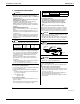
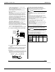
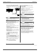
Connection example of whole system wiring7-1
Power
Remote
controller
Indoor
unit
Ground
Power
Ground
Outdoor unit
16V
208/230V
208/230V
16V
Ground fault
circuit interrupter
overcurrent
protective device
Branch switch
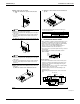
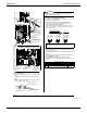
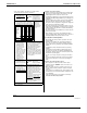
Routing power supply wiring and transmission 7-2
wiring
Let the power supply wiring with a conduit pass through one of
the knockout holes on the front or side cover, and let the
transmission wiring with a conduit pass through another
knockout hole.
For protection from uninsulated live parts, thread the power •
supply wiring or the transmission wiring through the included
insulating tube and secure it with the included clamp.
Insulating tube
(accessory)
Clamp
(accessory)
Power supply wiring
or
Transmission wiring
(3in.)
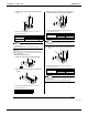
〈Precautions when knocking out knockout holes〉
To punch the knockout hole, hit it with a hammer.•
After removing the knockout hole, it is recommended that •
the edges should be painted to prevent rusting.
CAUTION
Use conduit for both the power supply wiring and transmis-•
sion wiring.
Outside the unit, make sure to keep the wirings 5 inches •
away.
Otherwise, the outdoor unit may be affected by electrical
noise (external noise), and malfunction or fail.
Be sure to connect the power supply wiring to the terminal •
block and secure it as described in “7-3 Power supply wiring
connection procedure”.
Fix the wiring between the units in accordance with •
“7-4 Transmission wiring connection procedure”.
Secure the wirings with the clamps (accessory) so that do •
not touch the piping.
Make sure the wirings will not be pinched by the front panel, •
and close the panel fi rmly.
Route the conduit along the unit by using a elbow socket •
and so on to prevent it from being stepped on.
Power supply wiring connection procedure7-3
WARNING
Never connect power supply wiring to the terminal block for
•
remote controller wiring as this could damage the entire system.
Install a ground fault circuit interruptER
sIs NECESSARYto install a ground fault circuit interrupter to
prevent electric shockSOR fi re accidentS.
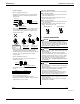
Model
Phase and
frequency
Voltage
Max.Overcurrent
Protective Device
Min. Circuit
Amps.
RZQ18PVJU
RZR18PVJU
~ 60Hz 208/230V 20A 16.5A
RZQ24PVJU
RZR24PVJU
RZQ30PVJU
RZR30PVJU