
Service Manual

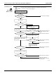
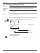

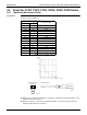
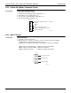
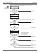
Table Of Contents
- Cover
- Table of contents
- Part 1 List of Functions
- Part 2 Specifications
- Part 3 Printed Circuit Board Connector Wiring Diagram
- Part 4 Refrigerant Circuit
- Part 5 Functions and Control
- Part 6 Test Operation and Field Settings
- Part 7 Remote Controller
- Part 8 Troubleshooting
- 1. Troubleshooting with LED
- 2. Service Diagnosis
- 3. Error Codes and Description
- 4. Troubleshooting for CTXG, CTXS, FTXS, CDXS, FDXS, FVXS Series
- 5. Troubleshooting for FFQ Series
- 6. Troubleshooting for Branch Provider (BP) Unit
- 7. Troubleshooting for Outdoor Unit
- 8. Thermistor Resistance/Temperature Characteristics
- 9. Pressure Sensor
- 10. Method of Replacing Inverter’s Power Transistors Modules
- Part 9 Appendix

SiUS181631EA Troubleshooting for CTXG, CTXS, FTXS, CDXS, FDXS, FVXS Series
Troubleshooting 205
4.6 Check for CTXG, CTXS, FTXS, CDXS, FDXS, FVXS Series
4.6.1 Thermistor Resistance Check
Check No.01 Disconnect the connectors of the thermistors from the PCB, and measure the resistance of each
thermistor using a multimeter.
The data is for reference purpose only.
When the room temperature thermistor is soldered on a PCB, remove the PCB from the control
PCB to measure the resistance.
When the connector of indoor heat exchanger thermistor is soldered on a PCB, remove the
thermistor and measure the resistance.
Thermistor temperature
Resistance (k
Ω
)
°C °F
–20 –4 197.8
–15 5 148.2
–10 14 112.1
–5 23 85.60
0 32 65.93
5 41 51.14
10 50 39.99
15 59 31.52
20 68 25.02
25 77 20.00
30 86 16.10
35 95 13.04
40 104 10.62
45 113 8.707
50 122 7.176
(R25°C (77°F) = 20 k
Ω
, B = 3950 K)
(kΩ)
150
100
50
–15 0 15 30 45
(R14467)
5 32 59 86 113
(˚C)
(˚F)
Multimeter
(R20505)
Room temperature
thermistor
Multimeter
Resistance range
Other thermistors
(R23371)