
Service Manual

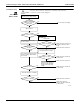
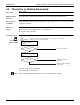

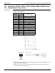
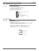
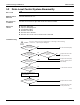
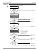
Table Of Contents
- Cover
- Table of contents
- Part 1 List of Functions
- Part 2 Specifications
- Part 3 Printed Circuit Board Connector Wiring Diagram
- Part 4 Refrigerant Circuit
- Part 5 Functions and Control
- Part 6 Test Operation and Field Settings
- Part 7 Remote Controller
- Part 8 Troubleshooting
- 1. Troubleshooting with LED
- 2. Service Diagnosis
- 3. Error Codes and Description
- 4. Troubleshooting for CTXG, CTXS, FTXS, CDXS, FDXS, FVXS Series
- 5. Troubleshooting for FFQ Series
- 6. Troubleshooting for Branch Provider (BP) Unit
- 7. Troubleshooting for Outdoor Unit
- 8. Thermistor Resistance/Temperature Characteristics
- 9. Pressure Sensor
- 10. Method of Replacing Inverter’s Power Transistors Modules
- Part 9 Appendix

Troubleshooting for CTXG, CTXS, FTXS, CDXS, FDXS, FVXS Series SiUS181631EA
206 Troubleshooting
4.6.2 Indoor Fan Motor Connector Check
Check No.02 CTXG, CTXS, FTXS, FVXS Series
1. Check the connection of connector.
2. Check motor power supply voltage output (pins 4 - 7).
3. Check motor control voltage (pins 4 - 3).
4. Check rotation command voltage output (pins 4 - 2).
5. Check rotation pulse input (pins 4 - 1).
4.6.3 Hall IC Check
Check No.04 CDXS, FDXS Series
1. Check the connector connection.
2. With the power on, operation off, and the connector connected, check the following.
(1) Output voltage of about 5 V between pins 1 and 3.
(2) Generation of 3 pulses between pins 2 and 3 when the fan motor is operating.
If NG in step (1)
Æ
Defective PCB
Æ
Replace the PCB (control PCB).
If NG in step (2)
Æ
Defective Hall IC
Æ
Replace the fan motor.
If OK in both steps (1) and (2)
Æ
Replace the PCB (control PCB).
7
6
5
4
3
2
1
S1 or S200
(R14225)
Motor power supply voltage (310 ~ 340 VDC)
Unused
Unused
GND
Motor control voltage (15 VDC)
Rotation command voltage (1~ 5 VDC)
Rotation pulse input
1
Gray (power supply)
Purple (signals)
Blue (grounding)
2
3
(R14211)
S7