
Service Manual
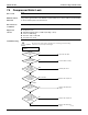
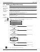
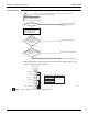
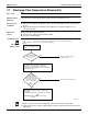
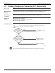
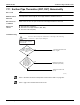
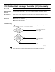
Table Of Contents
- Cover
- Table of contents
- Part 1 List of Functions
- Part 2 Specifications
- Part 3 Printed Circuit Board Connector Wiring Diagram
- Part 4 Refrigerant Circuit
- Part 5 Functions and Control
- Part 6 Test Operation and Field Settings
- Part 7 Remote Controller
- Part 8 Troubleshooting
- 1. Troubleshooting with LED
- 2. Service Diagnosis
- 3. Error Codes and Description
- 4. Troubleshooting for CTXG, CTXS, FTXS, CDXS, FDXS, FVXS Series
- 5. Troubleshooting for FFQ Series
- 6. Troubleshooting for Branch Provider (BP) Unit
- 7. Troubleshooting for Outdoor Unit
- 8. Thermistor Resistance/Temperature Characteristics
- 9. Pressure Sensor
- 10. Method of Replacing Inverter’s Power Transistors Modules
- Part 9 Appendix

Troubleshooting for Outdoor Unit SiUS181631EA
234 Troubleshooting
Troubleshooting
∗
1. Make measurement of resistance between the connector pins, and then make sure the
resistance falls in the range of 40 to 50
Ω
.
Note: Refer to page 175 for details about monitor mode.
(R23967)
YES
Turn power supply off, and
turn power supply on again.
The connector
of main PCB
(A1P) for electronic
expansion valve is
connected.
Replace the connecting cable.
Replace the main PCB (A1P).
YES
YES
NO
Ensure correct connection.
Could be other causes than
malfunction (for example,
noise etc.).
NO
The coil
resistance of electronic
expansion valve is normal.
(Refer to ∗1.)
NO
Identify the defective
electronic expansion valve
(Y1E or Y3E) in monitor
mode. (Refer to Note)
Return to normal?
Caution
Be sure to turn off the power switch before connecting or disconnecting
connectors, or parts may be damaged.
(R15616)
(Orange) 1
Measuring points
1 - 6
2 - 6
3 - 6
4 - 6
Judgment criteria
40 ~ 50 Ω
(Red) 2
(Yellow) 3
(Black) 4
(Gray) 5
COM + (White) 6
X21A, X22A
(Y1E, Y3E)