
Service Manual
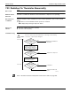

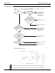
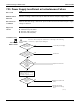

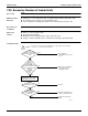
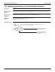
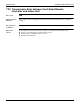
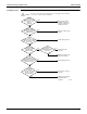
Table Of Contents
- Cover
- Table of contents
- Part 1 List of Functions
- Part 2 Specifications
- Part 3 Printed Circuit Board Connector Wiring Diagram
- Part 4 Refrigerant Circuit
- Part 5 Functions and Control
- Part 6 Test Operation and Field Settings
- Part 7 Remote Controller
- Part 8 Troubleshooting
- 1. Troubleshooting with LED
- 2. Service Diagnosis
- 3. Error Codes and Description
- 4. Troubleshooting for CTXG, CTXS, FTXS, CDXS, FDXS, FVXS Series
- 5. Troubleshooting for FFQ Series
- 6. Troubleshooting for Branch Provider (BP) Unit
- 7. Troubleshooting for Outdoor Unit
- 8. Thermistor Resistance/Temperature Characteristics
- 9. Pressure Sensor
- 10. Method of Replacing Inverter’s Power Transistors Modules
- Part 9 Appendix

SiUS181631EA Troubleshooting for Outdoor Unit
Troubleshooting 253
Troubleshooting
∗
1: Voltage measurement point
Refer to Thermistor Resistance/Temperature Characteristics table 1 on page 267.
For pressure/voltage characteristics graph, refer to Pressure Sensor on page 269.
Cooling?
Is the low
pressure sensor
correct?
The voltage
between the pins 2
and 3 of X18A is 1.0 VDC
or less? (Low pressure
sensor output
voltage)
∗1
Is the
suction pipe 1
temp. minus low pressure
saturation temp. 20˚C
(36˚F) or more?
Resistance is
normal when
measured after
disconnecting the
thermistor
(R3T).
Caution
Be sure to turn off the power switch before connecting or disconnecting
connectors, or parts may be damaged.
Low pressure is
0.25 MPa (84 ftAq)
or less?
Refrigerant shortage,
closed stop valve or
refrigerant system is
clogged. Check the
refrigerant system.
Replace the main PCB
(A1P).
(R23972)
YES YES
Replace the main PCB
(A1P).
YES
Refrigerant shortage or
refrigerant system is
clogged. Check the
refrigerant system.
YES
Replace the defective
thermistor.
NO
Replace the low pressure
sensor.
NO
NONO
NO
YES
YES
Replace the low pressure
sensor.
NO
Main PCB A1P
Low pressure sensor
Measure the voltage here.
Microcomputer
A/D input
+5V
X18A (Blue)
Red
(R13043)
Black
White
GND
(4)
(3)
(2)
(1)