
Service Manual

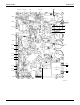
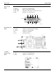
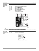
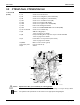
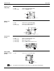
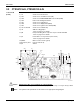
Table Of Contents
- Cover
- Table of contents
- Part 1 List of Functions
- Part 2 Specifications
- Part 3 Printed Circuit Board Connector Wiring Diagram
- Part 4 Refrigerant Circuit
- Part 5 Functions and Control
- Part 6 Test Operation and Field Settings
- Part 7 Remote Controller
- Part 8 Troubleshooting
- 1. Troubleshooting with LED
- 2. Service Diagnosis
- 3. Error Codes and Description
- 4. Troubleshooting for CTXG, CTXS, FTXS, CDXS, FDXS, FVXS Series
- 5. Troubleshooting for FFQ Series
- 6. Troubleshooting for Branch Provider (BP) Unit
- 7. Troubleshooting for Outdoor Unit
- 8. Thermistor Resistance/Temperature Characteristics
- 9. Pressure Sensor
- 10. Method of Replacing Inverter’s Power Transistors Modules
- Part 9 Appendix

Indoor Unit SiUS181631EA
28 Printed Circuit Board Connector Wiring Diagram
3.2 CTXS07JVJU, CTXS09/12HVJU
Control PCB
(PCB1)
Caution Replace the PCB if you accidentally cut a wrong jumper.
Jumpers are necessary for electronic circuit. Improper operation may occur if you cut any of them.
Note: The symbols in the parenthesis are the names on the appropriate wiring diagram.
1) S1 Connector for DC fan motor
2) S6 Connector for swing motor (horizontal blades)
3) S8 Connector for swing motor (vertical blades)
4) S21 Connector for centralized control (HA)
5) S26 Connector for buzzer PCB (PCB3)
6) S28 Connector for signal receiver PCB (PCB2)
7) S32 Indoor heat exchanger thermistor
8) S35 Connector for INTELLIGENT EYE sensor PCB (PCB5)
9) H1, H2, H3, FG Connector for terminal strip
10)JA Address setting jumper
∗
Refer to page 141 for details.
11)JB Fan speed setting when compressor stops for thermostat OFF
∗
Refer to page 143 for details.
12)JC Power failure recovery function (auto-restart)
∗
Refer to page 143 for details.
13)LED A LED for service monitor (green)
14)FU1 (Fu), FU3 Fuse (3.15 A, 250 V)
15)V1 Varistor
V1
FU1
S6
JC
JB
JA
S8
LED A
S21
S35
H1
S26S28
S1
S32
FG
H3
H2
FU3
2P290430-1