INSTALLATION MANUAL SPLIT SYSTEM Air Conditioners MODELS Ceiling Mounted Cassette type (Round Flow with Sensing Panel) FCQ18TAVJU FCQ24TAVJU FCQ30TAVJU FCQ36TAVJU FCQ42TAVJU FCQ48TAVJU English Français Español Read these instructions carefully before installation. Keep this manual in a handy place for future reference. This manual should be left with the equipment owner. Lire soigneusement ces instructions avant l’installation. Conserver ce manuel à portée de main pour référence ultérieure.
SPLIT SYSTEM Air Conditioners CONTENTS 1. SAFETY CONSIDERATIONS.................................[i] [ii] 2. BEFORE INSTALLATION............................................. 1 3. SELECTION OF INSTALLATION LOCATION............... 2 4. PREPARATION BEFORE INSTALLATION................... 4 5. INSTALLATION OF INDOOR UNIT.............................. 4 6. REFRIGERANT PIPING WORK................................... 6 7. DRAIN PIPING WORK................................................. 7 8. ELECTRIC WIRING WORK.
• This equipment can be installed with a Ground-Fault Circuit Interrupter (GFCI). Although this is a recognized measure for additional protection, with the grounding system in North America, a dedicated GFCI is not necessary. • When installing or relocating the system, keep the refrigerant circuit free from substances other than the specified refrigerant (R410A) such as air.
2. BEFORE INSTALLATION Name When unpacking the indoor unit or moving the unit after unpacked, hold the hangers (4 places) and do not apply force to other parts (particularly refrigerant piping, drain piping and resin parts). • Make sure to check in advance that the refrigerant to be used for installation work is R410A. The air conditioner will not operate properly without the correct refrigerant. • For installation of the outdoor unit, refer to the installation manual attached to the outdoor unit.
CARRY OUT THE WORK GIVING CAUTION TO THE FOLLOWING ITEMS AND AFTER THE WORK IS COMPLETED CHECK THESE AGAIN. (1) Items to be checked after completion of work (3) Points of the operation explanation In addition to the general usage, since the items in the operation manual with the WARNING and CAUTION marks are likely to result in human bodily injuries and property damages, it is necessary not only to explain these items to the customer but also to have the customer read them.
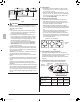
*60 (1,500) or more from a wall (NOTE 2) At least 60 (1,500) from any fixture Indoor unit (NOTE 1) Lighting Exhaust fan Indoor unit 60 (1,500) or more 80 (2,000) or more 160 (4,000) or more [unit: in. (mm)] Obstacles Fig. 2 CAUTION • Any vents, light fixtures, or other appliances which may disturb the airflow might stain the ceiling if too close, so follow Fig. 2 when installing. Note) 1.
4. PREPARATION BEFORE INSTALLATION (1) Check the relation of location between the ceiling opening and the indoor unit suspension bolts. [unit: in. (mm)] Frame Ceiling material Suspension bolt (×4) 5 Suspension bolt pitch 3 Indoor unit 2 Ceiling opening 1 Decoration panel A Fig. 4 [unit: in. (mm)] 1 37-3/8 (950) 2 33-7/8 – 35-7/8 (860 – 910) 3 33-1/16 (840) 4 30-3/4 (780) 5 28 (710) Hanger Ceiling View as seen from A Fig. 5 BYCQ125B-W1 BYCQ125BGW1 in.
(1) Install the indoor unit temporarily. • Connect the hangers to the suspension bolts. Be sure to use and tighten the nut and washer (3) for each hanger from both upper and lower sides of the hanger. (Refer to Fig. 7) If the washer fixing plate (7), the upper side washer for hanger (3) will be protected from falling off. (Refer to Fig. 8) [To fix hanger] (3) Adjust so that the unit will be properly positioned. (Refer to 4.
Tightening torque [lbf·ft. (N·m)] Dimension for processing flare A [in. (mm)] Flare shape [in. (mm)] f 3/8 (9.5) 24.1 – 29.4 (36.3±3.6) 0.504 – 0.520 (13.0±0.2) °± f 5/8 (15.9) 45.6 – 55.6 (68.6±6.8) 0.760 – 0.776 (19.5±0.2) 45 2° Piping size [in. (mm)] R0.016-0.031 (0.4-0.8) A • For the outdoor unit refrigerant piping, refer to the installation manual attached to the outdoor unit. • Carry out insulation of both gas and liquid refrigerant piping securely.
Gas side piping insulating method Joint insulating material (8) (accessory) Flare nut connection Piping insulating material (main unit) Bring the seam to the top. Wind around the piping until top of the flare nut connection, beginning at the base. Do not leave clearance. • Before brazing refrigerant piping, have nitrogen flow through the refrigerant piping and substitute air with nitrogen (NOTE 1) (Refer to Fig. 13). Then, carry out brazing (NOTE 2).
Support Downward inclination of 1/100 or more Tightened part approx. 90° 3–5 ft. (1–1.5 m) Vinyl tape Good Stick vinyl tape without tearing the sealing material (Large) (10) . Wrong Tightened part approx. 90° Fig. 14 CAUTION If drainage stagnates in the drain piping, the piping may get clogged. • If sufficient downward inclination cannot be ensured, carry out upward drain piping. • Install supports at a distance of 3–5 ft. (1–1.
CAUTION 0 to 26-1/2 in. (0 – 675 mm) • D o not apply excessive force to the attached drain hose (1) by bending or twisting it. This could cause water leakage. • In case of centralized drain piping, carry out piping work according to the procedure shown in the following Fig. 18. Sealing material (14) (accessory) Fig. 20 Centralized drain piping Make a downward inclination of 1/100 or more to avoid stagnancy of air. If water stagnates in the drain piping, it may cause clogging of drain piping. Fig.
4. When the power supply is turned on, the drain pump should operate. Drainage can be checked at the transparent part of the drain socket. (The drain pump will automatically stop after 10 minutes.) After checking the drainage of water, refer to Fig. 20 and attach the sealing material (14) to perform the thermal insulation of the drain socket. • Do not connect the drain piping directly to the sewage that gives off ammonia odor.
8-3 SPECIFICATION FOR FIELD SUPPLY FUSES AND WIRING Power supply wiring Model Fuse Remote controller wiring Transmission wiring Size Wire Size FCQ18TAVJU FCQ24TAVJU FCQ30TAVJU FCQ36TAVJU FCQ42TAVJU 15A 2-conductor, Wiring size stranded and length non-shielded AWG18-16 must copper cable (0.75comply PVC/vinyl 1.25 mm2) with local jacket codes. (NOTE) FCQ48TAVJU Allowable lengths of transmission wiring and remote controller wiring are as follows. (1) Outdoor unit – Indoor unit.....................
• Use a 90° elbow type of conduit with dimensions Fig. 23-1 to prevent it from hitting the swing motor housing of decoration panel. • Do not dispose the screw which assembles casing and resin together. The screw will be used to install conduit mounting plate. Make sure to install the conduit mounting plate first before wiring. Conduit mounting plate (17) Screw <1-3/8 (35) ≥3/8 (10) Fig.
Wiring penetrating hole 1.When using 1 remote controller (Normal operation) Power Supply 208/230V Outdoor unit 1~ 60Hz Control box Remote controller wiring/transmission wiring IN/D OUT/D F1 F2 F1 F2 L1 L2 Sealing material (Small) (13) (accessory) Putty or insulation (field supply) Fig.
8-6 FOR CONTROL WITH 2 REMOTE CONTROLLERS (TO CONTROL 1 INDOOR UNIT WITH 2 REMOTE CONTROLLERS) • For control with 2 remote controllers, set one remote controller as Main and the other remote controller as Sub. < Changeover method from Main to Sub and vice versa > Refer to the installation manual attached to the remote controller. < Wiring method > (1) Remove the control box cover.
10. FIELD SETTING <> CAUTION Before carrying out field setting, check the items mentioned in Clause 2: (1) Items to be checked after completion of work on page 2. Check if all the installation and piping works for the air conditioner are completed. • Check if the control box covers of the air conditioner are closed.
11. TEST OPERATION • The operation lamp of the remote controller will flash when a malfunction occurs. Check the malfunction code on the display to identify the point of trouble. An explanation of malfunction codes and the corresponding trouble is provided in “Service precautions” of the outdoor unit. If the display shows any of the following, there is a possibility that the wiring was done incorrectly or that the power is not on, so check again.
5151 San Felipe, Suite 500 Houston, TX 77056 3P161684-9U EM17A036 00_CV_3P161684-9U.