
Installation Manual
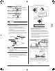
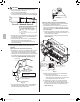
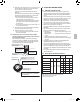
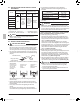

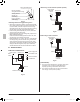
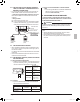
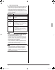
Table Of Contents

English
3/8 to 5/8 in.
(10 – 15 mm)
3/8 to 5/8 in.
(10 – 15 mm)
2-3/4 to 3-1/2 in.
(70 – 90 mm)
2-3/4 to 3-1/2 in.
(70 – 90 mm)
Approx.
1/4 in. (7 mm)
L
1
L
2
LN
Remote
controller wiring
Transmission
wiring
Forced
off
P1 P2 F1 F2 T1 T2
Ground
wiring
Ground terminal
Control box cover
[Remote controller wiring, Tr ansmission wiring]
[
Power supply wiring, Ground wiring
]
Sheathed part of
remote controller wiring,
transmission wiring
• Do not connect the power supply wiring (high voltage).
R10
or more
R10
or more
Strand the
wirings after
sheath is
peeled off.
After the wirings are clamped,
cut off the extra part.
After the
wirings are
clamped, cut
off the extra
part.
(Sheath peeling
off allowance.)
(Sheath peeling
off allowance.)
Clamp (4)
Clamp (4)
Wiring
penetrating
hole (low
voltage)
Te rminal block for
power supply wiring/
grounding wiring (3P)
Te rminal block for
remote controller wiring/
transmission wiring (X1M)
Wiring diagram label
(on backside of control box cover)
Printed Circuit
Board
Sheathed
part
Prohibited
Transmission
wiring
Remote
controller wiring
• Use a 90° elbow type of conduit with dimensions Fig. 23-1 to prevent it from hitting the swing motor hous-
ing of decoration panel.
• Do not dispose the screw which assembles casing and resin together. The screw will be used to install
conduit mounting plate. Make sure to install the conduit mounting plate first before wiring.
Fig. 23-1
Power supply and
ground wire
Conduit mounting
plate (17)
Insulation
tube (16)
Conduit mounting plate (17)
<1-3/8 (35)
≥
3/8 (10)
Screw
Fig. 23-2
12
01_EN_3P161684-9U.indd 12 8/8/2018 15:26:57