
Service Manual
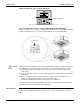
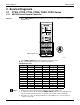
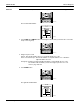
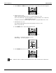
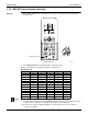

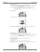
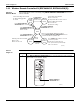
Table Of Contents
- Cover
- Table of contents
- Part 1 List of Functions
- Part 2 Specifications
- Part 3 Printed Circuit Board Connector Wiring Diagram
- Part 4 Refrigerant Circuit
- Part 5 Functions and Control
- Part 6 Test Operation and Field Settings
- Part 7 Remote Controller
- Part 8 Troubleshooting
- 1. Troubleshooting with LED
- 2. Service Diagnosis
- 3. Error Codes and Description
- 4. Troubleshooting for CTXG, CTXS, FTXS, CDXS, FDXS, FVXS Series
- 5. Troubleshooting for FFQ Series
- 6. Troubleshooting for Branch Provider (BP) Unit
- 7. Troubleshooting for Outdoor Unit
- 8. Thermistor Resistance/Temperature Characteristics
- 9. Pressure Sensor
- 10. Method of Replacing Inverter’s Power Transistors Modules
- Part 9 Appendix

SiUS181631EA Service Diagnosis
Troubleshooting 187
5. Diagnose by the sound.
★
beep: The left-side number does not correspond with the error code.
★
two consecutive beeps: The left-side number corresponds with the error code but the right-
side number does not.
★
long beep: Both the left-side and right-side numbers correspond with the error code.
The numbers indicated when you hear the long beep are the error code.
Refer to page 194, 195.
6. Press Mode button.
The right-side number blinks.
7. Press Temp ▲ or Temp ▼ button and change the number until you hear the long beep.
8. Diagnose by the sound.
★
beep: The left-side number does not correspond with the error code.
★
two consecutive beeps: The left-side number corresponds with the error code but the right-
side number does not.
★
long beep: Both the left-side and right-side numbers correspond with the error code.
9. Determine the error code.
The numbers indicated when you hear the long beep are the error code.
Refer to page 194, 195.
10. Press Mode button for 5 seconds to exit from the service check mode.
(When the remote controller is left untouched for 60 seconds, it returns to the normal mode
also.)
(R24047)
(R11673)
(R24048)
(R24047)