
Service Manual


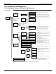
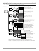

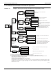
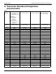
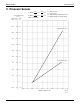
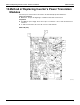
Table Of Contents
- Cover
- Table of contents
- Part 1 List of Functions
- Part 2 Specifications
- Part 3 Printed Circuit Board Connector Wiring Diagram
- Part 4 Refrigerant Circuit
- Part 5 Functions and Control
- Part 6 Test Operation and Field Settings
- Part 7 Remote Controller
- Part 8 Troubleshooting
- 1. Troubleshooting with LED
- 2. Service Diagnosis
- 3. Error Codes and Description
- 4. Troubleshooting for CTXG, CTXS, FTXS, CDXS, FDXS, FVXS Series
- 5. Troubleshooting for FFQ Series
- 6. Troubleshooting for Branch Provider (BP) Unit
- 7. Troubleshooting for Outdoor Unit
- 8. Thermistor Resistance/Temperature Characteristics
- 9. Pressure Sensor
- 10. Method of Replacing Inverter’s Power Transistors Modules
- Part 9 Appendix

Method of Replacing Inverter’s Power Transistors Modules SiUS181631EA
270 Troubleshooting
10.Method of Replacing Inverter’s Power Transistors
Modules
Check the power semiconductors mounted on the main PCB (A1P) with a multimeter.
Items to be prepared
z
Multimeter : Prepare the digital type of multimeter with diode check function.
Preparation
z
Turn OFF the power supply. Then, after a lapse of 10 minutes or more, make measurement of
resistance.
z
To make measurement, disconnect all connectors and terminals.
Main PCB (A1P)
(R13060)
C
–
C
+
W
V
U