
Service Manual
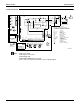
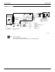
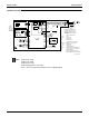
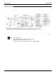
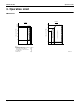

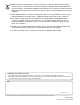
Table Of Contents
- Cover
- Table of contents
- Part 1 List of Functions
- Part 2 Specifications
- Part 3 Printed Circuit Board Connector Wiring Diagram
- Part 4 Refrigerant Circuit
- Part 5 Functions and Control
- Part 6 Test Operation and Field Settings
- Part 7 Remote Controller
- Part 8 Troubleshooting
- 1. Troubleshooting with LED
- 2. Service Diagnosis
- 3. Error Codes and Description
- 4. Troubleshooting for CTXG, CTXS, FTXS, CDXS, FDXS, FVXS Series
- 5. Troubleshooting for FFQ Series
- 6. Troubleshooting for Branch Provider (BP) Unit
- 7. Troubleshooting for Outdoor Unit
- 8. Thermistor Resistance/Temperature Characteristics
- 9. Pressure Sensor
- 10. Method of Replacing Inverter’s Power Transistors Modules
- Part 9 Appendix

SiUS181631EA Operation Limit
Appendix 287
3. Operation Limit
RMXS48LVJU
Heating
Cooling
120
60
115
104
50
41
80
60
40
23
5
73
50 57
57
82
82
Notes :
The graphs are based on the following conditions.
• Equivalent piping length
From outdoor unit to BP unit
From BP unit to each indoor units
• Level difference
• Air flow rate
16.4ft
9.8ft
0ft
High
Outdoor temp.
(˚
F
DB
)
Outdoor temp.
(˚
F
WB
)
Indoor temp.
(˚
F
WB
)
Indoor temp.
(˚
F
DB
)
Pull-down period
Warming
up
period
Continuous operation
Continuous operation
3D080742