
Service Manual
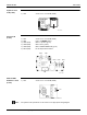
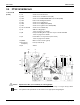
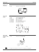
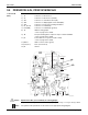
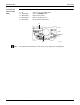
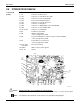
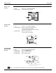
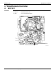
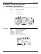
Table Of Contents
- Cover
- Table of contents
- Part 1 List of Functions
- Part 2 Specifications
- Part 3 Printed Circuit Board Connector Wiring Diagram
- Part 4 Refrigerant Circuit
- Part 5 Functions and Control
- Part 6 Test Operation and Field Settings
- Part 7 Remote Controller
- Part 8 Troubleshooting
- 1. Troubleshooting with LED
- 2. Service Diagnosis
- 3. Error Codes and Description
- 4. Troubleshooting for CTXG, CTXS, FTXS, CDXS, FDXS, FVXS Series
- 5. Troubleshooting for FFQ Series
- 6. Troubleshooting for Branch Provider (BP) Unit
- 7. Troubleshooting for Outdoor Unit
- 8. Thermistor Resistance/Temperature Characteristics
- 9. Pressure Sensor
- 10. Method of Replacing Inverter’s Power Transistors Modules
- Part 9 Appendix

SiUS181631EA Indoor Unit
Printed Circuit Board Connector Wiring Diagram 33
Signal Receiver
PCB (PCB2)
Display PCB
(PCB3)
INTELLIGENT
EYE Sensor PCB
(PCB4)
Note: The symbols in the parenthesis are the names on the appropriate wiring diagram.
1) S48 Connector for control PCB (PCB1)
3P224121-1
S48
1) S49 Connector for control PCB (PCB1)
2) SW1 Indoor unit ON/OFF button
3) LED1 (H1P) LED for operation (green)
4) LED2 (H2P) LED for timer (yellow)
5) LED3 (H3P) LED for INTELLIGENT EYE (green)
6) RTH1 (R1T) Room temperature thermistor
3P224121-1
RTH1 SW1
LED3 LED2 LED1
S49
1) S36 Connector for control PCB (PCB1)
S36
3P227885-1