SiEN04-306D Inverter Pair Wall Mounted Type B-Series [Applied Models] zInverter Pair : Cooling Only zInverter Pair : Heat Pump zNon-Inverter Pair : Cooling Only zNon-Inverter Pair : Heat Pump
SiEN04-306D Inverter Pair B-Series Cooling Only Indoor Unit FTKS50BVMA FTKS60BVMA FTKS71BVMA FTKD50BVM FTKD60BVM FTKD71BVM Outdoor Unit RKS50BVMA RKS60BVMA RKS71BVMA RKD50BVM RKD60BVM RKD71BVM FTKS50BVMB FTKS60BVMB FTKS71BVMB FTS50BVMB FTS60BVMB FTKS71BAVMB FTKD50BVMA FTKD60BVMA FTKD71BVMA FTKD50BVMT FTKD60BVMT FTKD71BVMT FTKD18BVMS FTKD24BVMS FTKD28BVMS RKS50BVMB(9) RKS50B2VMB RKS60BVMB(9) RKS60B2VMB RKS71BVMB(9) RKS71B2VMB RKS71B3VMB RS50BVMB RS60BVMB RS50B2VMB RS60B2VM
SiEN04-306D 1. Introduction .............................................................................................v 1.1 Safety Cautions ........................................................................................v Part 1 List of Functions ................................................................ 1 1. List of Functions ......................................................................................2 1.1 R-410A Series ..........................................................
SiEN04-306D 3.14 Forced Operation Mode .........................................................................69 3.15 Additional Function.................................................................................69 3.16 Facility Setting Switch (cooling at low outdoor temperature)..................70 Part 5 System Configuration....................................................... 71 1. System Configuration............................................................................72 2.
SiEN04-306D Part 7 Removal Procedure ........................................................ 147 1. Indoor Unit...........................................................................................148 1.1 1.2 1.3 1.4 1.5 1.6 Removal of the Air Filter / Front Panel .................................................148 Removal of the Front Grille ..................................................................151 Removal of the Horizontal Blades / Vertical Blades .............................
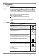
SiEN04-306D Introduction 1. Introduction 1.1 Safety Cautions Cautions and Warnings Be sure to read the following safety cautions before conducting repair work. The caution items are classified into “ Warning” and “ Caution”. The “ Warning” items are especially important since they can lead to death or serious injury if they are not followed closely. The “ Caution” items can also lead to serious accidents under some conditions if they are not followed.
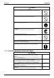
Introduction SiEN04-306D Caution Do not repair the electrical components with wet hands. Working on the equipment with wet hands can cause an electrical shock. Do not clean the air conditioner by splashing water. Washing the unit with water can cause an electrical shock. Be sure to provide the grounding when repairing the equipment in a humid or wet place, to avoid electrical shocks. Be sure to turn off the power switch and unplug the power cable when cleaning the equipment.
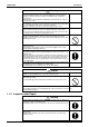
SiEN04-306D Introduction Warning Be sure to use an exclusive power circuit for the equipment, and follow the technical standards related to the electrical equipment, the internal wiring regulations and the instruction manual for installation when conducting electrical work. Insufficient power circuit capacity and improper electrical work can cause an electrical shock or fire. Be sure to use the specified cable to connect between the indoor and outdoor units.
Introduction SiEN04-306D Warning Do not use a joined power cable or extension cable, or share the same power outlet with other electrical appliances, since it can cause an electrical shock, excessive heat generation or fire. Caution Check to see if the parts and wires are mounted and connected properly, and if the connections at the soldered or crimped terminals are secure. Improper installation and connections can cause excessive heat generation, fire or an electrical shock.
SiEN04-306D Part 1 List of Functions 1. List of Functions ......................................................................................2 1.1 R-410A Series ..........................................................................................2 1.2 R22 Series................................................................................................
List of Functions SiEN04-306D 1.
-10H ~46 –10 ~46 Operation Limit for Heating (°CWB) — –15 ~18 Category Compressor — — Health & Clean Swing Compressor Rotary Compressor — — Power-Airflow Diffuser — — — — Wide-Angle Louvers — — Auto Fan Speed Worry Free “Reliability & Durability” Indoor Unit Silent Operation Operation — — — — — — Washable Grille — — Filter Cleaning Indicator — — Good-Sleep Cooling Operation — — — — Intelligent Eye Self-Diagnosis (Digital, LED) Display Wiring Error Check Anticorrosi
–10 ~46 –10 ~46 Operation Limit for Heating (°CWB) — –15 ~18 Category Compressor — — Health & Clean Swing Compressor Rotary Compressor — — Power-Airflow Diffuser — — — — Wide-Angle Louvers — — Auto Fan Speed Worry Free “Reliability & Durability” Indoor Unit Silent Operation Operation — — — — — — Washable Grille — — Filter Cleaning Indicator — — Good-Sleep Cooling Operation — — — — Intelligent Eye Self-Diagnosis (Digital, LED) Display Wiring Error Check Anticorrosio
–10 ~46 –10 ~46 Operation Limit for Heating (°CWB) — –15 ~18 Category Compressor — — Health & Clean Swing Compressor Rotary Compressor — — — — Power-Airflow Diffuser — — Wide-Angle Louvers — — Auto Fan Speed Worry Free “Reliability & Durability” Indoor Unit Silent Operation — — Intelligent Eye — — Washable Grille — — Filter Cleaning Indicator — — Good-Sleep Cooling Operation — — — — Self-Diagnosis (Digital, LED) Display Wiring Error Check Anticorrosion Treatment of Outd
–10 ~46 –10 ~46 Operation Limit for Heating (°CWB) –15 ~18 –15 ~18 Category Inverter (with Inverter Power Control) Basic Function Compressor — — Health & Clean Swing Compressor Rotary Compressor Comfortable Airflow — — Ultra-Longlife Filter (Option) — — Wipe-clean Flat Panel — — Timer — — Worry Free “Reliability & Durability” Indoor Unit Silent Operation — — — Filter Cleaning Indicator — — Good-Sleep Cooling Operation — — — — — — 10m 10m — — — — 24-Hour On/Off Time
Basic Function Compressor — — Operation Limit for Cooling (°CDB) –10 ~46 –10 ~46 Operation Limit for Heating (°CWB) — –15 ~18 PAM Control — — Oval Scroll Compressor — — — — Health & Clean — — — — Comfortable Airflow Wide-Angle Louvers Horizontal Auto-Swing (Right and Left) — — 3-D Airflow — — 3-Step Airflow (H/P Only) — — — — Auto Fan Speed Comfort Control — Longlife Filter — — Ultra-Longlife Filter (Option) — — — — Filter Cleaning Indicator — — Good-Sleep Co
List of Functions –5 ~46 –5 ~46 Operation Limit for Heating (°CWB) — –15 ~18 Category Inverter (with Inverter Power Control) Basic Function Compressor — — Health & Clean Swing Compressor Rotary Compressor — — — — Comfortable Airflow — — Wide-Angle Louvers Timer Vertical Auto-Swing (Up and Down) Horizontal Auto-Swing (Right and Left) — — Auto Fan Speed Worry Free “Reliability & Durability” Indoor Unit Silent Operation Night Quiet Mode (Automatic) Comfort Control — — Intelligent E
–5 ~46 –5 ~46 Operation Limit for Heating (°CWB) — –15 ~18 Category Inverter (with Inverter Power Control) Basic Function Compressor — — Health & Clean Swing Compressor Rotary Compressor — — Power-Airflow Diffuser — — — — Wide-Angle Louvers Timer Vertical Auto-Swing (Up and Down) Horizontal Auto-Swing (Right and Left) — — Auto Fan Speed Worry Free “Reliability & Durability” Indoor Unit Silent Operation Night Quiet Mode (Automatic) Comfort Control Operation — — — — Longlife Fil
Functions Category Inverter (with Inverter Power Control) Basic Function Operation Limit for Cooling (°CDB) 10~46 Operation Limit for Heating (°CWB) — Compressor — Swing Compressor Rotary Compressor Health & Clean — Power-Airflow Diffuser — — Wide-Angle Louvers Timer Vertical Auto-Swing (Up and Down) Horizontal Auto-Swing (Right and Left) — Auto Fan Speed Worry Free “Reliability & Durability” Indoor Unit Silent Operation Night Quiet Mode (Automatic) Comfort Control Operation — — Longl
Functions Category Inverter (with Inverter Power Control) Basic Function Operation Limit for Cooling (°CDB) –5 ~46 Operation Limit for Heating (°CWB) –15 ~18 Compressor — Health & Clean Swing Compressor Rotary Compressor — Power-Airflow Diffuser — Wide-Angle Louvers Timer Vertical Auto-Swing (Up and Down) Horizontal Auto-Swing (Right and Left) — Auto Fan Speed Worry Free “Reliability & Durability” Indoor Unit Silent Operation Night Quiet Mode (Automatic) — Intelligent Eye Flexibility
Functions Category Inverter (with Inverter Power Control) Basic Function Operation Limit for Cooling (°CDB) –5 ~46 Operation Limit for Heating (°CWB) –15 ~18 Compressor — Health & Clean Swing Compressor Rotary Compressor Power-Airflow Diffuser — — — Good-Sleep Cooling Operation — — Timer 24-Hour On/Off Timer Night Set Mode Auto-Restart (after Power Failure) — Auto Fan Speed Worry Free “Reliability & Durability” Indoor Unit Silent Operation — Outdoor Unit Silent Operation (Manual) Inte
SiEN04-306D Part 2 Specifications 1. Specifications ........................................................................................14 1.1 1.2 1.3 1.4 Specifications Cooling Only - R-410A Series ................................................................14 Cooling Only - R22 Series......................................................................18 Heat Pump - R-410A Series...................................................................22 Heat Pump - R22 Series .......................
Specifications SiEN04-306D 1. Specifications 1.1 Cooling Only - R-410A Series 50Hz 240V Model Indoor Units Outdoor Units Capacity Rated (Min.~Max.) Moisture Removal Running Current (Rated) Power Consumption Rated (Min.~Max.
SiEN04-306D Specifications 50Hz 230V Model Indoor Units Outdoor Units Capacity Rated (Min.~Max.) Moisture Removal Running Current (Rated) Power Consumption Rated (Min.~Max.
Specifications SiEN04-306D 50Hz 230V Model Indoor Units Outdoor Units Capacity Rated Moisture Removal Running Current (Rated) Power Consumption Rated Power Factor COP Liquid Piping Gas Connections Drain Heat Insulation Indoor Unit Front Panel Color m3/min (cfm) Air Flow Rate Type Motor Output Speed Air Direction Control Air Filter Running Current (Rated) Power Consumption (Rated) Power Factor Temperature Control Dimensions (H×W×D) Packaged Dimensions (H×W×D) Weight Gross Weight Operation H/L Sound Sou
SiEN04-306D Specifications 50Hz 230V Model Indoor Units Outdoor Units Capacity Rated (Min.~Max.) Moisture Removal Running Current (Rated) Power Consumption Rated (Min.~Max.
Specifications 1.2 SiEN04-306D Cooling Only - R22 Series 50Hz 220-230-240V / 60Hz 220-230V Model Indoor Units Outdoor Units kW Btu/h kcal/h L/h A Capacity Rated (Min.~Max.) Moisture Removal Running Current (Rated) Power Consumption Rated (Min.~Max.
SiEN04-306D Specifications 50Hz 220-230-240V / 60Hz 220-230V Model Indoor Units Outdoor Units kW Btu/h kcal/h L/h A Capacity Rated (Min.~Max.) Moisture Removal Running Current (Rated) Power Consumption Rated (Min.~Max.
Specifications SiEN04-306D 60Hz 220V Model Indoor Units Outdoor Units Cooling Capacity (Min.~Max.) Moisture Removal Running Current Power Consumption (Min.~Max.
SiEN04-306D Specifications 50Hz 220V Model Indoor Units Outdoor Units Capacity Rated (Min.~Max.) Moisture Removal Running Current (Rated) Power Consumption Rated (Min.~Max.
Specifications 1.3 SiEN04-306D Heat Pump - R-410A Series 50Hz 240V Indoor Units Model Capacity Rated (Min.~Max.) Moisture Removal Running Current (Rated) Power Consumption Rated (Min.~Max.
SiEN04-306D Specifications 50Hz 240V Indoor Units Model Capacity Rated (Min.~Max.) Moisture Removal Running Current (Rated) Power Consumption Rated (Min.~Max.
Specifications SiEN04-306D 50Hz 230V Indoor Units Model Capacity Rated (Min.~Max.) Moisture Removal Running Current (Rated) Power Consumption Rated (Min.~Max.
SiEN04-306D Specifications 50Hz 230V Indoor Units Model Capacity Rated (Min.~Max.) Moisture Removal Running Current (Rated) Power Consumption Rated (Min.~Max.
Specifications SiEN04-306D 50Hz 230V Indoor Units Model Capacity Rated (Min.~Max.) Moisture Removal Running Current (Rated) Power Consumption Rated (Min.~Max.
SiEN04-306D Specifications 50Hz 230V Indoor Units Model ATXS50DVMB ARXS50C(2)VMB Outdoor Units Capacity Rated (Min.~Max.) Moisture Removal Running Current (Rated) Power Consumption Rated (Min.~Max.
Specifications SiEN04-306D 50Hz 230V Indoor Units Model Capacity Rated Moisture Removal Running Current (Rated) Power Consumption Rated Power Factor COP Liquid Piping Gas Connections Drain Heat Insulation Indoor Unit Front Panel Color 3/min Air Flow Rate m (cfm) Type Motor Output Speed Air Direction Control Air Filter Running Current (Rated) Power Consumption (Rated) Power Factor Temperature Control Dimensions (H×W×D) Packaged Dimensions (H×W×D) Weight Gross Weight Operation H/L Sound Sound Power H Outd
SiEN04-306D 1.4 Specifications Heat Pump - R22 Series 50Hz 220-230-240V / 60Hz 220-230V Indoor Units Model FTXD50BVMA RXD50BVMA Outdoor Units Capacity Rated (Min.~Max.) Moisture Removal Running Current (Rated) Power Consumption Rated (Min.~Max.
Specifications SiEN04-306D 50Hz 220-230-240V / 60Hz 220-230V Indoor Units Model Capacity Rated (Min.~Max.) Moisture Removal Running Current (Rated) Power Consumption Rated (Min.~Max.
SiEN04-306D Specifications 60Hz 220V Indoor Units Model FTXD50BVMT RXD50BVMT Outdoor Units Capacity (Min.~Max.) Moisture Removal Running Current Power Consumption (Min.~Max.
Specifications SiEN04-306D 60Hz 220V Indoor Units Model Capacity (Min.~Max.) Moisture Removal Running Current Power Consumption (Min.~Max.
SiEN04-306D Specifications 50Hz 240V Indoor Unit Model Capacity Rated (Min.~Max.) Moisture Removal Running Current (Rated) Power Consumption Rated (Min.~Max.
Specifications SiEN04-306D 50Hz 240V Indoor Units Model Capacity Rated (Min.~Max.) Moisture Removal Running Current (Rated) Power Consumption Rated (Min.~Max.
SiEN04-306D Part 3 Printed Circuit Board Connector Wiring Diagram 1. Printed Circuit Board Connector Wiring Diagram..................................36 1.1 Indoor Unit..............................................................................................36 1.2 Outdoor Unit ...........................................................................................
Printed Circuit Board Connector Wiring Diagram SiEN04-306D 1. Printed Circuit Board Connector Wiring Diagram 1.
SiEN04-306D PCB Detail Printed Circuit Board Connector Wiring Diagram PCB(1): Control PCB (indoor unit) S1 V1 FU1 S21 S6 S8 S35 LEDA JA JB JC PCB(2): Signal Receiver PCB S32 S28 S26 (R2860) PCB(3): Buzzer PCB S27 SW1 S38 S29 (R2861) RTH1 PCB(4): Display PCB LED1 LED2 (R2862) PCB(5): Intelligent Eye sensor PCB LED3 S37 (R2863) S36 (R2864) Printed Circuit Board Connector Wiring Diagram 37
Printed Circuit Board Connector Wiring Diagram 1.
SiEN04-306D PCB Detail Printed Circuit Board Connector Wiring Diagram PCB(1): Control PCB (outdoor unit) E AC1 FU2(3.
Printed Circuit Board Connector Wiring Diagram SiEN04-306D MID S34 S72 FU201 (3.
SiEN04-306D Part 4 Function and Control 1. Main Functions......................................................................................42 1.1 1.2 1.3 1.4 1.5 1.6 1.7 1.8 1.9 1.10 1.11 Frequency Principle................................................................................42 Power-Airflow Dual Flaps, Wide Angle Louvers and Auto-Swing ..........44 Fan Speed Control for Indoor Units........................................................45 Programme Dry Function ...........................
SiEN04-306D Part 5 System Configuration 1. System Configuration............................................................................72 2. Instruction..............................................................................................73 2.1 2.2 2.3 2.4 2.5 2.6 2.7 2.8 2.9 2.10 2.11 2.12 System Configuration Safety Precautions .................................................................................73 Names of Parts...................................................................
Main Functions SiEN04-306D 1. Main Functions Note: 1.1 See the list of functions for the functions applicable to different models. Frequency Principle Main Control Parameters The compressor is frequency-controlled during normal operation.
SiEN04-306D Inverter Features Main Functions The inverter provides the following features: The regulating capacity can be changed according to the changes in the outside temperature and cooling/heating load. Quick heating and quick cooling The compressor rotational speed is increased when starting the heating (or cooling). This enables a quick set temperature.
Main Functions 1.2 SiEN04-306D Power-Airflow Dual Flaps, Wide Angle Louvers and Auto-Swing Power-airflow Dual Flaps The large flaps send a large volume of air downwards to the floor. The flap provides an optimum control area in cooling, heating and dry mode. Heating Mode During heating mode, the large flap enables direct warm air straight downwards. The flap presses the warm air above the floor to reach the entire room. Cooling Mode During cooling mode, the flap retracts into the indoor unit.
SiEN04-306D 1.3 Main Functions Fan Speed Control for Indoor Units Control Mode The airflow rate can be automatically controlled depending on the difference between the set temperature and the room temperature. This is done through phase control and Hall IC control. For more information about Hall IC, refer to the troubleshooting for fan motor on page 111. Phase Steps Phase control and fan speed control contains 9 steps: LLL, LL, SL, L, ML, M, MH, H and HH.
Main Functions 1.4 SiEN04-306D Programme Dry Function Programme dry function removes humidity while preventing the room temperature from lowering. Since the microcomputer controls both the temperature and air flow volume, the temperature adjustment and fan adjustment buttons are inoperable in this mode. In Case of Inverter Units The microcomputer automatically sets the temperature and fan settings.
SiEN04-306D 1.5 Main Functions Automatic Operation Automatic Cooling / Heating Function (Heat Pump Only) When the AUTO mode is selected with the remote control, the microcomputer automatically determines the operation mode from cooling and heating according to the room temperature and setting temperature at the time of the operation startup, and automatically operates in that mode.
Main Functions 1.6 SiEN04-306D Thermostat Control Thermostat control is based on the difference between the room temperature and the setpoint. Thermostat OFF Condition The temperature difference is in the zone A. Thermostat ON Condition The temperature difference is above the zone C after being in the zone A. The system resumes from defrost control in any zones except A. The operation turns on in any zones except A. The monitoring time has passed while the temperature difference is in the zone B.
SiEN04-306D 1.7 Main Functions Night Set Mode When the OFF timer is set, the Night Set circuit automatically activates. The Night Set circuit maintains the airflow setting made by users. The Night Set Circuit The Night Set circuit continues heating or cooling the room at the set temperature for the first one hour, then automatically raises the temperature setting slightly in the case of cooling, or lowers it slightly in the case of heating, for economical operations.
Main Functions 1.8 SiEN04-306D INTELLIGENT EYE This is the function that detects existence of humans in the room by a human motion sensor (INTELLIGENT EYE) and reduces the capacity when there is no human in the room in order to save electricity. Processing 1. Detection method by INTELLIGENT EYE sampling (20msec) Sensor output 1sec If the sensor detects the outputs 10 times/sec. or more, it judges humans exist.
SiEN04-306D Main Functions Since the set temperature is shifted by 2°C higher for 40 minutes, compressor speed becomes low and can realize energy saving operation. But as thermostat is prone to be off by the fact that the set temperature has been shifted, the thermostat-off action is prohibited in 40 minutes so as to prevent this phenomena.
Main Functions 1.9 SiEN04-306D HOME LEAVE Operation Outline In order to respond to the customer's need for immediate heating and cooling of the room after returning home or for house care, a measure to switch the temperature and air volume from that for normal time over to outing time by one touch is provided. (This function responds also to the need for keeping up with weak cooling or heating.
SiEN04-306D Main Functions 1.10 Inverter POWERFUL Operation Outline In order to exploit the cooling and heating capacity to full extent, operate the air conditioner by increasing the indoor fan rotating speed and the compressor frequency. Details of the Control When POWERFUL button is pushed in each operation mode, the fan speed/setting temperature will be converted to the following states in a period of twenty minutes.
Main Functions SiEN04-306D 1.11 Other Functions 1.11.1 Hot Start Function Heat Pump Only In order to prevent the cold air blast that normally comes when heating is started, the temperature of the heat exchanger of the indoor unit is detected, and either the air flow is stopped or is made very weak thereby carrying out comfortable heating of the room. *The cold air blast is also prevented using a similar control when the defrosting operation is started or when the thermostat gets turned ON. 1.11.
SiEN04-306D Function of Main Structural Parts 2. Function of Main Structural Parts 2.1 Function of Thermistor 2.1.1 Heat Pump Model A Electronic expansion valve C Four way valve B Compressor (R5318) A Outdoor Heat Exchanger Thermistor 1. The outdoor heat exchanger thermistor is used for controlling target discharge temperature. Set a target discharge temperature depending on the outdoor and indoor heat exchanger temperature.
Function of Main Structural Parts SiEN04-306D 2.1.2 Cooling Only Model A Electrontic expansion valve C B Compressor (R2828) A Outdoor Heat Exchanger Thermistor 1. The outdoor heat exchanger thermistor is used for controlling target discharge temperature. Set a target discharge temperature depending on the outdoor and indoor heat exchanger temperature. Control the electronic expansion valve opening so that the target discharge temperature can be obtained. 2.
SiEN04-306D Control Specification 3. Control Specification 3.1 Mode Hierarchy Outline There are two modes; the mode selected in user’s place (normal air conditioning mode) and forced operation mode for installation and providing service. Detail 1.
Control Specification 3.2 Outline SiEN04-306D Frequency Control Frequency will be determined according to the difference between room and set temperature. The function is explained as follows. 1. How to determine frequency. 2. Frequency command from an indoor unit. (The difference between a room temperature and the temperature set by the remote control.) 3. Frequency command from an indoor unit. 4. Frequency initial setting. 5. PI control.
SiEN04-306D Control Specification 3. Determine lower limit frequency Set a maximum value as an lower limit frequency among the frequency lower limits of the following functions: Pressure difference upkeep. 4. Determine prohibited frequency There is a certain prohibited frequency such as a power supply frequency. Indoor Frequency Command (ΔD signal) The difference between a room temperature and the temperature set by the remote control will be taken as the “ΔD signal” and is used for frequency command.
Control Specification 3.3 SiEN04-306D Controls at Mode Changing / Start-up 3.3.1 Preheating Operation Outline Operate the inverter in the open phase operation with the conditions including the preheating command from the indoor, the outdoor air temperature and discharge pipe temperature. Detail Preheating ON Condition When outdoor air temperature is below 10.5°C and discharge pipe temperature is below 10.5°C, inverter in open phase operation starts.
SiEN04-306D 3.4 Control Specification Discharge Pipe Temperature Control Outline The discharge pipe temperature is used as the compressor's internal temperature. If the discharge pipe temperature rises above a certain level, the operating frequency upper limit is set to keep this temperature from going up further.
Control Specification 3.6 SiEN04-306D Freeze-up Protection Control Outline During cooling operation, the signals being sent from the indoor unit allow the operating frequency limitation and then prevent freezing of the indoor heat exchanger. (The signal from the indoor unit must be divided into the zones as the followings. Detail Conditions for Start Controlling Judge the controlling start with the indoor heat exchanger temperature after 2 sec from operation start.
SiEN04-306D 3.8 Control Specification Fan Control Outline Fan control is carried out according to the following priority. 1. Fan ON control for electric component cooling fan 2. Fan control when defrosting 3. Fan OFF delay when stopped 4. ON/OFF control in cooling operation 5. Tap control when drooping function is working 6. Fan control in forced operation 7. Fan control in indoor/outdoor unit silent operation 8. Fan control in powerful mode 9.
Control Specification SiEN04-306D 3.10 Low Hz High Pressure Limit Outline Heat Pump Only Set the upper limit of high pressure in a low Hz zone. Set the upper limit of the indoor heat exchanger temperature by its operating frequency of Hz. Separate into three zones, reset zone, unchanged zone and drooping zone and the frequency control must be carried out in such zones.
SiEN04-306D Control Specification 3.12 Electronic Expansion Valve Control Detail The followings are the examples of control which function in each mode by the electronic expansion valve control.
Control Specification SiEN04-306D 3.12.1 Fully Closing with Power ON Initialize the electronic expansion valve when turning on the power, set the opening position and develop pressure equalizing. 3.12.2 Pressure Equalization Control When the compressor is stopped, open and close the electronic expansion valve and develop pressure equalization. 3.12.3 Opening Limit Outline Limit a maximum and minimum opening of the electronic expansion valve.
SiEN04-306D Control Specification 3.12.7 Control when frequency is changed When the target discharge pipe temperature control is active, if the target frequency is changed for a specified value in a certain time period, cancel the target discharge pipe temperature control and change the target opening of the electronic expansion valve according to the shift. 3.12.
Control Specification SiEN04-306D 3.13 Malfunctions 3.13.1 Sensor Malfunction Detection Sensor malfunction may occur either in the thermistor or current transformer (CT) system. Relating to Thermistor Malfunction 1. Outdoor heat exchanger thermistor 2. Discharge pipe thermistor 3. Fin thermistor 4. Outside air thermistor Relating to CT Malfunction When the output frequency is more than 55 Hz and the input current is less than 1.25A, carry out abnormal adjustment. 3.13.
SiEN04-306D Control Specification 3.14 Forced Operation Mode Outline Forced operating mode includes only forced cooling. Detail Forced Cooling Item Forced operation allowing conditions Starting/adjustment 1) Command frequency 2) Electronic expansion valve opening 3) Outdoor unit adjustment 4) Indoor unit adjustment End Others Forced Cooling 1) The outdoor unit is not abnormal and not in the 3-minute stand-by mode. 2) The operating mode of the outdoor unit is the stop mode.
Control Specification SiEN04-306D 3.16 Facility Setting Switch (cooling at low outdoor temperature) Outline RKS50/60/71BVMB9, RK(X)S71B2(3)VMB models This function is limited only for facilities (the target of air conditioning is equipment (such as computer)). Never use it in a residence or office (the space where there is a human). Detail You can expand the operation range to –15°C by turning on switch B (SW4) on the PCB. If the outdoor temperature falls to –20°C or lower, the operation will stop.
System Configuration SiEN04-306D 3. System Configuration After the installation and test operation of the room air conditioner have been completed, it should be operated and handled as described below. Every user would like to know the correct method of operation of the room air conditioner, to check if it is capable of cooling (or heating) well, and to know a clever method of using it.
SiEN04-306D Instruction 4. Instruction Note: This instruction is appropriate for FTK(X)S 50/60/71 B(A)VMB models. 4.1 Safety Precautions • • • • Keep this manual where the operator can easily find them. Read this manual attentively before starting up the unit. For safety reason the operator must read the following cautions carefully. This manual classifies precautions into WARNINGS and CAUTIONS. Be sure to follow all precautions below: they are all important for ensuring safety.
Instruction SiEN04-306D • • • • • • • • • To avoid oxygen deficiency, ventilate the room sufficiently if equipment with burner is used together with the air conditioner. Before cleaning, be sure to stop the operation, turn the breaker off or pull out the supply cord. Do not connect the air conditioner to a power supply different from the one as specified. It may cause trouble or fire. Depending on the environment, an earth leakage breaker must be installed.
SiEN04-306D 4.
Instruction SiEN04-306D Outdoor Unit Indoor Unit 1. Air filter 2. Air-Purifying Filter with photocatalytic deodorizing function • These filters are attached to the inside of the air filters. 3. Air inlet 4. Front panel 5. Panel tab 6. INTELLIGENT EYE sensor: • It detects the movements of people and automatically switches between normal operation and energy saving operation. (page 18) 7. Display 8. Air outlet 9. Flap (horizontal blade): (page 12) 10.
SiEN04-306D Instruction Remote control 1 2 5 3 6 4 9 11 7 8 12 10 16 13 17 15 14 1. Signal transmitter: • It sends signals to the indoor unit. 2. Display: • It displays the current settings. (In this illustration, each section is shown with its displays ON for the purpose of explanation.) 3. HOME LEAVE button: HOME LEAVE operation (page 16) 4. POWERFUL button: POWERFUL operation (page 14) 5. TEMPERATURE adjustment buttons: • It changes the temperature setting. 6.
Instruction 4.3 SiEN04-306D Preparation Before Operation To set the batteries 1. Slide the front cover to take it off. 2. Set two dry batteries (AAA). 3. Set the front cover as before. Position + and – correctly! 2 – + + – 3 1 ATTENTION • • • • • • 78 About batteries When replacing the batteries, use batteries of the same type, and replace the two old batteries together. When the system is not used for a long time, take the batteries out.
SiEN04-306D Instruction To operate the remote control • • • To use the remote control, aim the transmitter at the indoor unit. If there is anything to block signals between the unit and the remote control, such as a curtain, the unit will not operate. Do not drop the remote control. Do not get it wet. The maximum distance for communication is about 7m. Reciever To fix the remote control holder on the wall 1. Choose a place from where the signals reach the unit. 2.
Instruction SiEN04-306D To set the clock 1. Press “CLOCK button”. 0:00 is displayed. blinks. 2. Press “TIMER setting button” to set the clock to the present time. Holding down “ ” or “ ” button rapidly increases or decreases the time display. 3. Press “CLOCK button”. blinks. : Turn the breaker ON • Turning ON the breaker opens the flap, then closes it again. (This is a normal procedure.) C HOME LEAVE POWERFUL MODE SILENT ON/OFF TEMP FAN SENSOR SWING 2 ON CANCEL 1.
SiEN04-306D 4.4 Instruction AUTO · DRY · COOL · HEAT · FAN Operation The air conditioner operates with the operation mode of your choice. From the next time on, the air conditioner will operate with the same operation mode. To start operation 1. Press “MODE selector button” and select a operation mode. • • Each pressing of the button advances the mode setting in sequence. : AUTO : DRY : COOL : HEAT : FAN 2. Press “ON/OFF button” . • The OPERATION lamp lights up.
Instruction SiEN04-306D To change the air flow rate setting 5. Press “FAN setting button”. DRY mode AUTO or COOL or HEAT or FAN mode Five levels of air flow rate setting from “ ” to “ plus “ ”“ ” ” are available. The air flow rate setting is not variable • Indoor unit quiet operation When the air flow is set to “ ”, the noise from the indoor unit will become quieter. Use this when making the noise quieter. The unit might lose capacity when the air flow rate is set to a weak level.
SiEN04-306D 4.5 Instruction Adjusting the Air Flow Direction You can adjust the air flow direction to increase your comfort.. To adjust the horizontal blade (flap) 1. Press “SWING button ”. • “ ” is displayed on the LCD 2. When the flaps have reached the desired position, press “SWING button ” once more. • The flap will stop moving. ON C HOME LEAVE POWERFUL MODE SILENT ON/OFF TEMP FAN SENSOR SWING ON CANCEL OFF TIMER To adjust the vertical blades (louvers) 3. Press “SWING button ”.
Instruction SiEN04-306D To 3-D Airflow 1. 3. Press the “SWING button ” and the “SWING button ”: the “ ” and “ ” display will light up and the flap and louvers will move in turn. To cancel 3-D Airflow 2. 4. Press either the “SWING button ” or the “SWING button ”. Notes on louvers angles • ATTENTION Always use a remote control to adjust the louvers angles. In side the air outlet, a fan is rotating at a high speed. Notes on flap angle • In COOL or DRY mode STOP COOL approx. 10˚~40˚ DRY approx.
SiEN04-306D 4.6 Instruction POWERFUL Operation POWERFUL operation quickly maximizes the cooling (heating) effect in any operation mode. You can get the maximum capacity To start POWERFUL operation 1. Press “POWERFUL button”. • POWERFUL operation ends in 20 minutes. Then the system automatically operates again with the settings which were used before POWERFUL operation. • When using POWERFUL operation, there are some functions which are not available.
Instruction 4.7 SiEN04-306D OUTDOOR UNIT SILENT Operation OUTDOOR UNIT SILENT operation lowers the noise level of the outdoor unit by changing the frequency and fan speed on the outdoor unit. This function is convenient during night. To start OUTDOOR UNIT SILENT operation 1. Press “SILENT button”. C To cancel OUTDOOR UNIT SILENT operation 2. Press “SILENT button”.
SiEN04-306D 4.8 Instruction HOME LEAVE Operation HOME LEAVE operation is a function which allows you to record your preferred temperature and air flow rate settings. To start HOME LEAVE operation 1. Press “HOME LEAVE button”. • The HOME LEAVE lamp lights up. 1, 2 To cancel HOME LEAVE operation 2. Press “HOME LEAVE button” again. • The HOME LEAVE lamp goes off.
Instruction SiEN04-306D What’s the HOME LEAVE operation Is there a set temperature and air flow rate which is most comfortable, a set temperature and air flow rate which you use the most? HOME LEAVE operation is a function that allows you to record your favorite set temperature and air flow rate. You can start your favorite operation mode simply by pressing the HOME LEAVE button on the remote control. This function is convenient in the following situations. Useful in these cases. 1.
SiEN04-306D 4.9 Instruction INTELLIGENT EYE Operation “INTELLIGENT EYE” is the infrared sensor which detects the human movement. To start INTELLIGENT EYE operation 1. Press “SENSOR button”. To cancel the INTELLIGENT EYE operation C 2. Press “SENSOR button” again. [EX.] When somebody in the room HOME LEAVE • Normal operation POWERFUL When nobody in the room • 20 min. after, start energy operation.
Instruction SiEN04-306D “INTELLIGENT EYE” is useful for Energy Saving Energy saving operation • Change the temperature –2°C in heating / +2°C in cooling / +1°C in dry mode from set temperature. • Decrease the air flow rate slightly in fan operation. (In FAN mode only) Notes on “INTELLIGENT EYE” • Application range is as follows. Vertical angle 90° (Side View) Horizontal angle 110° (Top View) • • • • • 90° 7m 55° 55° 7m Sensor may not detect moving objects further than 7m away.
SiEN04-306D Instruction 4.10 TIMER Operation Timer functions are useful for automatically switching the air conditioner on or off at night or in the morning. You can also use OFF TIMER and ON TIMER in combination. To use OFF TIMER operation • Check that the clock is correct. If not, set the clock to the present time. 1. Press “OFF TIMER button”. 0:00 is displayed. blinks. 2. Press “TIMER Setting button” until the time setting reaches the point you like.
Instruction SiEN04-306D To use ON TIMER operation • Check that the clock is correct. If not, set the clock to the present time. (page 9) 1. Press “ON TIMER button”. • 6:00 is displayed. • “ “blinks. 2. 2.Press “TIMER Setting button” until the time setting reaches the point you like. • Every pressing of either button increases or decreases the time setting by 10 minutes. Holding down either button changes the setting rapidly. 3. 3.Press “ON TIMER button” again. • The TIMER lamp lights up..
SiEN04-306D Instruction 4.11 Care and cleaning CAUTION Before cleaning, be sure to stop the operation and turn the breaker OFF. UNITS Indoor unit, Outdoor unit and Remote control 1. Wipe them with dry soft cloth. Front grille 1. Open the front grille. • Hold the grille by the tabs on the two sides and lift it until it stops with a click. 2. Remove the front grille. • Open the front panel further while sliding it to either the left or right and pulling it toward you.
Instruction SiEN04-306D FILTERS 1. Open the front panel. (page 24) 2. Pull out the air filters. • Push a little upwards the tab at the center of each air filter, then pull it down. 3. Take off the Air purifying filter with photocatalytic deodorizing function. • Press the top of the air-cleaning filter onto the tabs (3 tabs at top). Then press the bottom of the filter up slightly, and press it onto the tabs (2 at bottom) (3 at bottom).
SiEN04-306D Instruction Check Check that the base, stand and other fittings of the outdoor unit are not decayed or corroded. Check that nothing blocks the air inlets and the outlets of the indoor unit and the outdoor unit. Check that the drain comes smoothly out of the drain hose during COOL or DRY operation • If no drain water is seen, water may be leaking from the indoor unit. Stop operation and consult the service shop if this is the case. Before a long idle period 1.
Instruction SiEN04-306D 4.12 Troubleshooting These cases are not troubles The following cases are not air conditioner troubles but have some reasons. You may just continue using it. Case Explanation Operation does not start soon. • When ON/OFF button was pressed soon after operation was stopped. • When the mode was reselected. • This is to protect the air conditioner.You should wait for about 3 minutes. Hot air does not flow out soon after the start of heating operation.
SiEN04-306D Instruction Check again Please check again before calling a repair person. Case The air conditioner does not operate. (OPERATION lamp is off) Cooling (Heating) effect is poor Operation stops suddenly. (OPERATION lamp flashes.) An abnormal functioning happens during operation.
Instruction SiEN04-306D Call the service shop immediately. WARNING When an abnormality (such as a burning smell) occurs, stop operation and turn the breaker OFF. Continued operation in an abnormal condition may result in troubles, electric shocks or fire. Consult the service shop where you bought the air conditioner. Do not attempt to repair or modify the air conditioner by yourself. Incorrect work may result in electric shocks or fire. Consult the service shop where you bought the air conditioner.
SiEN04-306D Instruction Fault diagnosis by remote control. In the ARC433A series, the temperature display sections on the main unit indicate corresponding codes. 1. When the TIMER CANCEL button is held down for 5 seconds, a “00” indication flashes on the temperature display section. ON C HOME LEAVE POWERFUL MODE SILENT ON/OFF TEMP FAN SENSOR SWING ON CANCEL OFF TIMER 2. Press the TIMER CANCEL button repeatedly until a continuous beep is produced.
Instruction 100 SiEN04-306D System Configuration
SiEN04-306D Part 6 Service Diagnosis 1. 2. 3. 4. Caution for Diagnosis..........................................................................102 Problem Symptoms and Measures .....................................................103 Service Check Function ......................................................................104 Troubleshooting ..................................................................................107 4.1 4.2 4.3 4.4 4.5 4.6 4.7 4.8 4.9 4.10 4.11 4.12 4.13 4.14 4.15 4.16 4.
Caution for Diagnosis SiEN04-306D 1. Caution for Diagnosis The Operation lamp flashes when any of the following errors is detected. 1. When a protection device of the indoor or outdoor unit is activated or when the thermistor malfunctions, disabling equipment operation. 2. When a signal transmission error occurs between the indoor and outdoor units. In either case, conduct the diagnostic procedure described in the following pages.
SiEN04-306D Problem Symptoms and Measures 2. Problem Symptoms and Measures Symptom Check Item None of the units operates. Check the power supply. Check the type of the indoor units. Check the outdoor air temperature. Operation sometimes stops. Equipment operates but does not cool, or does not heat (only for heat pump model). Large operating noise and vibrations Service Diagnosis Details of Measure Check to make sure that the rated voltage is supplied.
Service Check Function SiEN04-306D 3. Service Check Function In the ARC433A series remote control, the temperature display sections on the main unit indicate corresponding codes. Check Method 1 1. When the timer cancel button is held down for 5 seconds, a “00” indication flashes on the temperature display section. ON C HOME LEAVE POWERFUL MODE SILENT ON/OFF TEMP FAN SENSOR SWING ON CANCEL TIMER CANCEL button It cancels the timer setting. OFF TIMER < ARC433A21, A22 > (R2839) 2.
SiEN04-306D Service Check Function Check Method 2 1. Enter the diagnosis mode. Press the 3 buttons (TEMPs,TEMPt, MODE) simultaneously. (R4272) The digit of the number of tens blinks. HTry again from the start when the digit does not blink. (R4273) 2. Press the TEMP button. Press TEMPs or TEMPt and change the digit until you hear the sound of “beep” or “pi pi”. (R4274) 3. Diagnose by the sound. H“pi” : The number of tens does not accord with the error code.
Service Check Function SiEN04-306D 5. Press the TEMP button. Press TEMPs or TEMPt and change the digit until you hear the sound of “beep”. (R4277) 6. Diagnose by the sound. H“pi” : The both numbers of tens and units do not accord with the error code. H“pi pi” : The number of tens accords with the error code. H“beep” : The both numbers of tens and units accord with the error code. 7. Determine the error code. The digits indicated when you hear the “beep” sound are error code.
SiEN04-306D Troubleshooting 4. Troubleshooting 4.
Troubleshooting 4.2 SiEN04-306D Indoor Unit PCB Abnormality remote control Display A1 Method of Malfunction Detection Evaluation of zero-cross detection of power supply by indoor unit. Malfunction Decision Conditions When there is no zero-cross detection in approximately 10 continuous seconds. Supposed Causes Faulty indoor unit PCB Faulty connector connection Troubleshooting Caution Be sure to turn off power switch before connect or disconnect connector, or parts damage may be occurred.
SiEN04-306D 4.3 Troubleshooting Freeze-up Protection Control or High Pressure Control remote control Display A5 Method of Malfunction Detection High pressure control (heat pump model only) During heating operations, the temperature detected by the indoor heat exchanger thermistor is used for the high pressure control (stop, outdoor fan stop, etc.
Troubleshooting SiEN04-306D Troubleshooting Caution Check No.6 Refer to P.141 Be sure to turn off power switch before connect or disconnect connector, or parts damage may be occurred. Check the air passage. Is there any short-circuit? YES Provide sufficient air passage. NO Check the intake air filter. Is it very dirty? YES Clean the air filter. NO Check the dust accumulation on the indoor unit heat exchanger. Is it very dirty? YES Clean the heat exchanger. NO Check No.
SiEN04-306D 4.4 Troubleshooting Fan Motor (DC Motor) or Related Abnormality remote control Display A6 Method of Malfunction Detection The rotation speed detected by the Hall IC during fan motor operation is used to determine abnormal fan motor operation. Malfunction Decision Conditions When the detected rotation speed does not reach the demanded rotation speed of the target tap, and is less than 50% of the maximum fan motor rotation speed.
Troubleshooting SiEN04-306D Troubleshooting Caution Check No.01 Refer to P.139 Be sure to turn off power switch before connect or disconnect connector, or parts damage may be occurred. Turn off power supply and rotate fan by hand. Does fan rotate smoothly? NO Replace fan motor. YES Turn power ON and operate fan. Does it rotate? Turn off power supply NO and disconnect fan motor connector, then turn power ON. YES Check No.
SiEN04-306D 4.5 Troubleshooting Thermistor or Related Abnormality (Indoor Unit) remote control Display C4, C9 Method of Malfunction Detection The temperatures detected by the thermistors are used to determine thermistor errors. Malfunction Decision Conditions When the thermistor input is more than 4.96 V or less than 0.04 V during compressor operation∗. ∗ (reference) When above about 212°C (less than 120 ohms) or below about –50°C (more than 1,860 kohms).
Troubleshooting 4.6 SiEN04-306D Signal Transmission Error (between Indoor and Outdoor Units) remote control Display U4 Method of Malfunction Detection The data received from the outdoor unit in indoor unit-outdoor unit signal transmission is checked whether it is normal. Malfunction Decision Conditions When the data sent from the outdoor unit cannot be received normally, or when the content of the data is abnormal. Supposed Causes Faulty outdoor unit PCB. Faulty indoor unit PCB.
SiEN04-306D 4.7 Troubleshooting OL Activation (Compressor Overload) remote control Display E5 Method of Malfunction Detection A compressor overload is detected through compressor OL. Malfunction Decision Conditions If the compressor OL is activated twice, the system will be shut down. The error counter will reset itself if this or any other error does not occur during the following 60-minute compressor running time (total time). ∗ The operating temperature condition is not specified.
Troubleshooting 4.8 SiEN04-306D Compressor Lock remote control Display E6 Method of Malfunction Detection A compressor lock is detected by checking the compressor running condition through the position detection circuit. Malfunction Decision Conditions The position detection circuit detects a compressor frequency of below 10 Hz for 20 seconds or a frequency of above 160 Hz. 40 seconds after the compressor has started, the position detection circuit detects a compressor frequency of above 180 Hz.
SiEN04-306D 4.9 Troubleshooting DC Fan Lock remote control Display E7 Method of Malfunction Detection A fan motor or related error is detected by checking the high-voltage fan motor rpm being detected by the Hall IC. Malfunction Decision Conditions The fan does not start in 30 seconds even when the fan motor is running. The system will be shut down if the error occurs 16 times.
Troubleshooting SiEN04-306D 4.10 Input Over Current Detection remote control Display E8 Method of Malfunction Detection An input over-current is detected by checking the input current value being detected by CT with the compressor running. Malfunction Decision Conditions The following CT input with the compressor running continues for 2.5 seconds. CT input : Above 20 A The system will be shut down if the error occurs 16 times.
SiEN04-306D Troubleshooting Troubleshooting Caution Check No.7 Refer to P.142 Check No.8 Refer to P.143 Be sure to turn off power switch before connect or disconnect connector, or parts damage may be occurred. ∗ An input over-current may result from wrong internal wiring. If the wires have been disconnected and reconnected for part replacement, for example, and the system is interrupted by an input over-current, take the following procedure. Get restarted and measure the input current.
Troubleshooting SiEN04-306D 4.11 Four Way Valve Abnormality remote control Display EA Method of Malfunction Detection The room temperature thermistor, the indoor unit heat exchanger thermistor, the outdoor temperature thermistor and the outdoor unit heat exchanger thermistor are checked to see if they function within their normal ranges in the operating mode. Malfunction Decision Conditions A following condition continues over 1 minute after operating 10 minutes. Cooling / dry operation (room temp.
SiEN04-306D Troubleshooting Troubleshooting Caution Check No.5 Refer to P.140 Check No.6 Refer to P.141 Be sure to turn off power switch before connect or disconnect connector, or parts damage may be occurred. Four way valve coil disconnected (loose)? YES NO YES Harness out of connector? Check No.11 Refer to P.144 Correct. Reconnect. NO Check the continuity of the four way valve coil and harness. Disconnect the harness from the connector.
Troubleshooting SiEN04-306D 4.12 Discharge Pipe Temperature Control remote control Display F3 Method of Malfunction Detection The discharge pipe temperature control (stop, frequency drooping, etc.) is checked with the temperature being detected by the discharge pipe thermistor. Malfunction Decision Conditions If a stop takes place 6 times successively due to abnormal discharge pipe temperature, the system will be shut down.
SiEN04-306D Troubleshooting 4.13 High Pressure Control in Cooling remote control Display F6 Method of Malfunction Detection High-pressure control (stop, frequency drop, etc.) is activated in the cooling mode if the temperature being sensed by the heat exchanger thermistor exceeds the limit. Malfunction Decision Conditions Activated when the temperature being sensed by the heat exchanger thermistor rises above 60°C. (Deactivated when the said temperature drops below 50°C.
Troubleshooting SiEN04-306D Troubleshooting Caution Check No.4 Refer to P.139 Check No.6 Refer to P.141 Be sure to turn off power switch before connect or disconnect connector, or parts damage may be occurred. Check the installation space. Check No.7 Installation condition check Abnormal Normal Check No.7 Refer to P.142 Check No.9 Outdoor fan check Abnormal Normal Check No.9 Refer to P.143 Change the air outlet grille position. Change the installation location. Clean the heat exchanger.
SiEN04-306D Troubleshooting 4.14 Position Sensor Abnormality remote control Display H6 Method of Malfunction Detection A compressor startup failure is detected by checking the compressor running condition through the position detection circuit. Malfunction Decision Conditions The compressor fails to start in about 15 seconds after the compressor run command signal is sent. Clearing condition: Continuous run for about 5 minutes (normal) The system will be shut down if the error occurs 16 times.
Troubleshooting SiEN04-306D 4.15 CT or Related Abnormality remote control Display H8 Method of Malfunction Detection A CT or related error is detected by checking the compressor running frequency and CTdetected input current. Malfunction Decision Conditions The compressor running frequency is below 55 Hz and the CT input is below 0.1 V. (The input current is also below 1.25 A.) If this error repeats 4 times, the system will be shut down.
SiEN04-306D Troubleshooting Troubleshooting Caution Check No.12 Refer to P.145 Be sure to turn off power switch before connect or disconnect connector, or parts damage may be occurred. Turn off the power and turn it on again. Get the system started. ∗ Running current as shown at right with relay cable 1 or 2? YES Current (guideline) NO Check No. 12 Check the capacitor voltage. Rising with increasing frequency 2 sec DC380±30V? Replace the outdoor unit PCB.
Troubleshooting SiEN04-306D 4.16 Thermistor or Related Abnormality (Outdoor Unit) remote control Display P4, J3, J6, H9 Method of Malfunction Detection This type of error is detected by checking the thermistor input voltage to the microcomputer. [A thermistor error is detected by checking the temperature.] Malfunction Decision Conditions The thermistor input is above 4.96 V or below 0.04 V with the power on.
SiEN04-306D Troubleshooting Troubleshooting Caution Check No.6 Refer to P.141 Be sure to turn off power switch before connect or disconnect connector, or parts damage may be occurred. Turn on the power again. Error displayed again on remote controller? NO Reconnect. YES Connector or thermistor disconnected? YES Reconnect. NO Check No. 6 Check the thermistor resistance value. NO Normal? YES Replace defective one(s) of the following thermistors.
Troubleshooting SiEN04-306D 4.17 Electrical Box Temperature Rise remote control Display L3 Method of Malfunction Detection An electrical box temperature rise is detected by checking the radiation fin thermistor with the compressor off. Malfunction Decision Conditions With the compressor off, the radiation fin temperature is above 80°C (above 75°C in the case of 7.1kW class). (Reset is made when the temperature drops below 70°C.
SiEN04-306D Troubleshooting Troubleshooting Caution Check No.6 Refer to P.141 Be sure to turn off power switch before connect or disconnect connector, or parts damage may be occurred. Turn off the power and turn it on again. Check No.7 Refer to P.142 Error again or outdoor unit fan activated? Check No.9 Refer to P.143 WARNING To cool down the electricals, the outdoor unit fan gets started when the radiation fin temperature rises above 80˚C and stops itself when it drops below 70˚C. YES NO Check No.
Troubleshooting SiEN04-306D 4.18 Radiation Fin Temperature Rise remote control Display L4 Method of Malfunction Detection A radiation fin temperature rise is detected by checking the radiation fin thermistor with the compressor on. Malfunction Decision Conditions If the radiation fin temperature with the compressor on is above 90°C, If a radiation fin temperature rise takes place 4 times successively, the system will be shut down.
SiEN04-306D Troubleshooting Troubleshooting Check No.6 Refer to P.141 Caution Be sure to turn off power switch before connect or disconnect connector, or parts damage may be occurred. Turn off the power and turn it on again to get the system started. Check No.7 Refer to P.142 Error displayed again? Check No.9 Refer to P.143 YES NO Check No. 6 Check the thermistor resistance value. z Fin thermistor Check the radiation fin temperature.
Troubleshooting SiEN04-306D 4.19 Output Over Current Detection remote control Display L5 Method of Malfunction Detection An output over-current is detected by checking the current that flows in the inverter DC section. Malfunction Decision Conditions A position signal error occurs while the compressor is running. A speed error occurs while the compressor is running. An output over-current input is fed from the output over-current detection circuit to the microcomputer.
SiEN04-306D Troubleshooting Troubleshooting Caution Check No.7 Refer to P.142 Be sure to turn off power switch before connect or disconnect connector, or parts damage may be occurred. ∗ An output over-current may result from wrong internal wiring. If the wires have been disconnected and reconnected for part replacement, for example, and the system is interrupted by an output over-current, take the following procedure. NO Stop valve fully open? Check No.8 Refer to P.143 Check No.13 Refer to P.
Troubleshooting SiEN04-306D 4.20 Insufficient Gas remote control Display U0 Method of Malfunction Detection Gas shortage detection I : A gas shortage is detected by checking the CT-detected input current value and the compressor running frequency. Gas shortage detection II : A gas shortage is detected by checking the difference between indoor unit heat exchanger temperature and room temperature as well as the difference between outdoor unit heat exchanger temperature and room temperature.
SiEN04-306D Troubleshooting Troubleshooting Caution Check No.4 Refer to P.139 Check No.6 Refer to P.141 Be sure to turn off power switch before connect or disconnect connector, or parts damage may be occurred. Any thermistor disconnected? NO YES Reconnect in position. * Discharge pipe thermistor * Indoor / outdoor unit heat exchanger thermistor * Room temperature thermistor * Outdoor air thermistor YES Open the stop valve. Stop valve closed? NO Check for gas leakage.
Troubleshooting SiEN04-306D 4.21 Low-voltage Detection remote control Display U2 Method of Malfunction Detection An abnormal voltage rise or drop is detected by checking the detection circuit or DC voltage detection circuit. Malfunction Decision Conditions An over-voltage signal is fed from the over-voltage detection circuit to the microcomputer, or the voltage being detected by the DC voltage detection circuit is judged to be below 150 V for 0.1 second.
SiEN04-306D Check 5. Check 5.1 How to Check 5.1.1 Fan Motor Connector Output Check Check No.01 1. 2. 3. 4. 5. Check connector connection. Check motor power supply voltage output (pins 4-7). Check motor control voltage (pins 4-3). Check rotation command voltage output (pins 4-2). Check rotation pulse input (pins 4-1). S1 7 6 5 4 3 2 1 Motor power supply voltage Unused Unused P.0V (reference potential) Motor control voltage (15 VDC) Rotation command voltage (1~ 6 VDC) Rotation pulse input (R3199) 5.1.
Check SiEN04-306D 5.1.3 Four Way Valve Performance Check Check No.5 Turn off the power and turn it on again. Start the heating-mode run. S80 voltage at DC 180-220 V with compressor on? (Fig. 1) ∗ Four way valve coil Cooling / dry : No continuity Heating : Continuity NO Replace the outdoor unit PCB. YES Disconnect the four way valve coil from the connector and check the continuity. Four way valve coil resistance at 1500 ohms? NO YES Replace the four way valve coil. Replace the four way valve.
SiEN04-306D Check 5.1.4 Thermistor Resistance Check Check No.6 Remove the connectors of the thermistors on the PCB, and measure the resistance of each thermistor using tester. The relationship between normal temperature and resistance is shown in the graph and the table below. Thermistor R25°C=20kΩ B=3950 Temperature (°C) –20 –15 –10 –5 0 5 10 15 20 25 30 35 40 45 50 211.0 (kΩ) 150 116.5 88 67.2 51.9 40 31.8 25 20 16 13 10.6 8.7 7.
Check SiEN04-306D 5.1.5 Installation Condition Check Check No.7 Installation condition check Check the allowable dimensions of the air suction and discharge area. Normal Does the discharged air from other outdoor unit cause an increase of the suction air temperature? Abnormal YES Change the position of the air discharge grille or the installation location. Change the position of the air discharge grille or the installation location.
SiEN04-306D Check 5.1.6 Discharge Pressure Check Check No.8 Discharge pressure check NO High Replace compessor. YES Is the stop valve open? NO Open the stop valve. YES Is the connection pipe deformed? NO Replace the pipe installed at the site. YES At the heat exchanger and air filter dirty? NO Clean. YES Replace the compressor. (R1443) 5.1.7 Outdoor Unit Fan System Check (With DC Motor) Check No.9 Check the outdoor unit fan system.
Check SiEN04-306D 5.1.8 Power Supply Waveforms Check Check No.10 Measure the power supply waveform between pins 1 and 3 on the terminal board, and check the waveform disturbance. Check to see if the power supply waveform is a sine wave (Fig.1). Check to see if there is waveform disturbance near the zero cross (sections circled in Fig.2) [Fig.1] [Fig.2] (R1444) (R1736) 5.1.9 Inverter Units Refrigerant System Check Check No.
SiEN04-306D Check 5.1.10 Capacitor Voltage Check Check No.12 Before this checking, be sure to check the main circuit for short-circuit. Checking the capacitor voltage With the circuit breaker still on, measure the voltage according to the drawing of the model in question. Be careful never to touch any live parts. Use the tester in the DC range.
Check SiEN04-306D 5.1.12 Main Circuit Electrolytic Capacitor Check Check No.14 Checking the main circuit electrolytic capacitor Never touch any live parts for at least 10 minutes after turning off the circuit breaker. If unavoidably necessary to touch a live part, make sure there is no DC voltage using the tester. Check the continuity with the tester. Reverse the pins and make sure there is continuity. Keep the tester in the resistancer measuring range.
SiEN04-306D Part 7 Removal Procedure 1. Indoor Unit...........................................................................................148 1.1 1.2 1.3 1.4 1.5 1.6 Removal of the Air Filter / Front Panel .................................................148 Removal of the Front Grille ..................................................................151 Removal of the Horizontal Blades / Vertical Blades .............................153 Removal of the Electrical Box / PCB / Swing Motor ...............
Indoor Unit SiEN04-306D 1. Indoor Unit 1.1 Removal of the Air Filter / Front Panel Procedure Warning Be sure to wait 10 minutes or more after turning off all power supplies before disassembling work. Procedure Step Points 1. Features Room temperature sensor (thermistor) (R2746) Operation lamp Signal receiver When the signal receiver catches a signal from the remote control, it produces beep sound and the operation lamp blinks. Timer lamp ON/OFF switch (R2747) 2. Remove the air filters.
SiEN04-306D Step Indoor Unit Procedure Points The right and left filters are interchangeable. Insert the air filters along grooves when installing. Set the air filters with displaying “FRONT” on the front side. Insert two claws of the air filter completely. “FRONT” Claws 3. Remove an “air purifying filter with photocatalytic deodorizing function”. 1 Push up the bottom of an air purifying filter to undo the claws (2 on lower, 3 on upper) and take the filter out.
Indoor Unit Step SiEN04-306D Procedure Points 4. Remove the front panel. 1 While opening the front panel further than it stops, release both axes and remove the front panel. Slide the front panel side to side to release each axis. Align the right and left axes with grooves in turn and insert them to the end when installing.
SiEN04-306D 1.2 Indoor Unit Removal of the Front Grille Procedure Step Warning Be sure to wait 10 minutes or more after turning off all power supplies before disassembling work. Procedure Points 1. Remove the service cover. 1 Loosen the screw and remove the service cover by the knob. Service cover (R2756) No field setting switch is inside it. You can remove the front grille without detaching the service cover. 2. Remove the front grille. 1 Loosen the three fixing screws of the front grille.
Indoor Unit Procedure Step 2 SiEN04-306D Undo the three hooks on the top of the front grille. Points The front grille has three hooks on the center and the both sides of the upper part. Refer to the removal procedure in a reverse way when reassembling. Hook (R2759) Hook (R2760) 3 152 Pull the upper part of the front grille out and lift the lower part up, and then remove the front grille. Make sure that all the hooks are placed securely when reassembling.
SiEN04-306D 1.3 Indoor Unit Removal of the Horizontal Blades / Vertical Blades Procedure Warning Be sure to wait 10 minutes or more after turning off all power supplies before disassembling work. Procedure Step Points 1. Remove the horizontal blades. 1 Open the horizontal blades. It has no fixing screws inside blades, though previous models had. Horizontal blades (R2763) 2 Undo the left pivot of the horizontal blades.
Indoor Unit SiEN04-306D Procedure Step 2. Remove the vertical blades. 1 Undo the right and left pivots. Points Vertical blades (R2767) 2 Undo the three claws. Claws (R2768) 3 154 Pull the vertical blades rightwards and remove it.
SiEN04-306D 1.4 Indoor Unit Removal of the Electrical Box / PCB / Swing Motor Procedure Step Warning Be sure to wait 10 minutes or more after turning off all power supplies before disassembling work. Procedure Points 1. Remove the front grille. Parts layout 2. Remove the drip proof plate. 1 Loosen the screw. Drip proof plate (R2771) 3. Disconnect the indoor heat exchanger thermistor and the earth. Mind that not to lose the clip for the thermistor.
Indoor Unit SiEN04-306D Procedure Step 4. Remove the electrical box. 1 Disconnect the four connection wirings. Loosen the screw and remove the terminal strip board. Points You can remove the electrical box without detaching the terminal strip board. Terminal strip board Screw: M4×25 (R2773) 2 Disconnect the connectors for fan motor (S1). Connector for fan motor S1 (R2774) 3 Disconnect the connectors for swing motor (S6, S8).
SiEN04-306D Indoor Unit Procedure Step Points 5 Dislocate the electrical box to the left and undo the back claw. The electrical box has a claw on its back. 6 Pull the electrical box out towards you. Hook the back claw of the electrical box when reassembling. 7 Loosen the screw on the electrical box. Screw: M4×16 8 Push the shelter up and undo the claw.
Indoor Unit Procedure Step 9 SiEN04-306D Points Press the receiver units down and release the claws on the upper side, and then undo the claws on the lower side. Release the claws on the upper side. Receiver units (R2781) 10 Cut the clamp. 11 The receiver units contain four PCBs. Remove each PCB with releasing claws. Disconnect every connector from each PCB. Display PCB Intelligent Eye sensor PCB 12 158 Cut the clamp. Remove the receiver units while pushing the claws of connectors.
SiEN04-306D Indoor Unit Procedure Step 5. Remove the control PCB. 1 Undo the two claws on the lower side, and then the two claws on the upper side. Remove the control PCB. Points Upper claws Lower claws Control PCB (R2783) 2 Control PCB (indoor unit) S1: connector for the fan motor S21: HA S26: connector for the room temperature thermistor S32: connector for the heat exchanger thermistor V1 (varsitor) FU1 (soldered) 250 V 3.15A 6. Remove the swing motor for horizontal blades.
Indoor Unit SiEN04-306D Procedure Step Points 7. Remove the swing motor for vertical blades. 1 Release the swing axis on the right side. Releasing the swing axis (1)Undo the claw (2)Pull it out (R2790) 2 Loosen the two screws and detach the swing motor assembly. (R2791) Swing motor assembly 3 Loosen the two screws and remove the swing motor. Six claws hold the assembly.
SiEN04-306D 1.5 Indoor Unit Removal of the Heat Exchanger Procedure Warning Be sure to wait 10 minutes or more after turning off all power supplies before disassembling work. Procedure Step Points Remove the electrical box. 1. Disconnect the refrigerant piping. 1 Hold the indoor unit up by a piece of wood etc.. Caution If gas leaks, repair the spot of leaking, then collect all refrigerant from the unit. After conducting vacuum drying, recharge proper amount of refrigerant.
Indoor Unit Step SiEN04-306D Procedure Points 2. Remove the indoor unit. 1 Detach the indoor unit from the installation plate. 3. Remove the piping fixture. 1 Release the claw on the upper side of the piping fixture on the back of the unit. Piping fixture (R2798) 4. Remove the heat exchanger. 1 Widen the auxiliary piping to the extent of 10°~20°.
SiEN04-306D Procedure Step 2 Indoor Unit Points Release the claws on the left side. Claws (R2800) 3 Push the fixing claws on the right side and release. Claws (R2801) 4 Pull the heat exchanger to the front side and undo the claws completely, and then lift it. Caution When removing or reinstalling heat exchanger, be sure to wear protective gloves or wrap the heat exchanger with cloths. (Fins can cut fingers.
Indoor Unit 1.6 SiEN04-306D Removal of the Fan Rotor / Fan Motor Procedure Warning Be sure to wait 10 minutes or more after turning off all power supplies before disassembling work. Procedure Step Points 1. Remove the right side panel. 1 Loosen the two screws. You can remove the fan rotor without detaching the right side panel. Right side panel (R2803) 2 Lift the right side panel and remove it. 2. Remove the fan rotor. 1 Loosen the screw and remove the fan motor fixture.
SiEN04-306D Indoor Unit Procedure Step Points 3. Remove the fan motor. 1 Remove the fan motor. Reassembling the fan motor (1) When reassembling the fan rotor, provide as much as 5mm of play between the side face of the rotor and the bottom frame. Fan motor (R2807) Side face of bottom frame Side face of rotor 4. Remove the bearing. 1 Remove the fan rotor. The bearing is on the left side.
Outdoor Unit SiEN04-306D 2. Outdoor Unit 2.1 Removal of the Panels and Plates Procedure Warning Be sure to wait 10 minutes or more after turning off all power supplies before disassembling work. Procedure Step Points 1. Remove the panels and plates. 1 Loosen the four screws and lift the top panel. Top panel (R2676) Outdoor air thermistor Take care not to cut your finger by the fins of the heat exchanger. Heat exchanger (R2677) 2 Loosen the four screws and remove the discharge grille.
SiEN04-306D Outdoor Unit Procedure Step Points The front grille has four claws. Slide the discharge grille upwards and remove it. 3 Loosen the six screws of the front panel. Front panel (R2680) 4 Push the front panel and undo the claw. Lift the clamp plate and remove it.
Outdoor Unit Procedure Step 5 SiEN04-306D Undo the right side claw, and then the left side claws. Remove the front panel. Points Lift the front panel and remove it while pushing the right side panel inwards. Lift the front panel and undo the left side claws. Fit the left side of the front panel first when installing.
SiEN04-306D Outdoor Unit Procedure Step Points 2. Remove the stop valve cover. 1 Loosen the screw of the stop valve cover. Stop valve cover (R2685) 2 Pull down the stop valve cover to undo the claws and remove it. The stop valve cover has six claws.
Outdoor Unit 2.2 SiEN04-306D Removal of the Fan Motor / Propeller Fan Procedure Warning Be sure to wait 10 minutes or more after turning off all power supplies before disassembling work. Procedure Step Remove the top panel and the front panel. 1. Remove the electrical box cover. 1 Loosen the screw on the back of the shelter. Points Shelter This procedure is not necessary to remove the propeller fan only. Claws (R2688) 2 Undo the two claws and remove it.
SiEN04-306D Outdoor Unit Procedure Step 2. Remove the fan motor. 1 Disconnect the connector for fan motor (S70). Points S70 (R2692) 2 The illustration shows arrangement of the fan motor lead wire.
Outdoor Unit Procedure Step 3 SiEN04-306D Points Unscrew the washerfitted nut (M10) of the propeller fan with a spanner. Propeller fan (R2694) Align mark of the propeller fan with D-cut section of the motor shaft when reassembling. 4 Remove the four screws from the fan motor.
SiEN04-306D Procedure Step 5 Outdoor Unit Pull the fan motor out. Points Put the lead wire through the back of the motor when reassembling.
Outdoor Unit 2.3 SiEN04-306D Removal of the PCB / Electrical Box Procedure Warning Be sure to wait 10 minutes or more after turning off all power supplies before disassembling work. Procedure Step Remove the top panel and the front panel. 1. Remove the right side panel. 1 Disconnect the three connection wirings and the two earth wires.
SiEN04-306D Step Outdoor Unit Procedure Points the t Claw hen reassembling. (R2701) Claws 2. Disconnect harnesses. 1 Loosen the fixing screw of the cable way board.
Outdoor Unit SiEN04-306D Procedure Step 2 Push the claw up to release the cable way board. Open the cable way board. 3 Disconnect the harnesses from the power supply PCB. HL (black) ···· to the terminal strip HE2 (yellow / green) ···· to the terminal strip (earth) HAC1 (black) ···· from the control PCB (AC1) HE1 (yellow / green) ···· from the control PCB (E) 4 Disconnect the connectors of the front side.
SiEN04-306D Outdoor Unit Procedure Step 5 6 Loosen the screw of the control PCB. Points Control PCB Undo the two claws and release the control PCB from the ditch of the front side. Ditch (R2703) 7 Disconnect the harnesses while opening the control PCB. S10: to the terminal strip AC2: to the terminal strip S10 AC2(white) (R2710) 8 Disconnect the connectors.
Outdoor Unit SiEN04-306D Procedure Step 9 Disconnect the connectors.
SiEN04-306D Outdoor Unit Procedure Step 11 Disconnect the relaying wire connector for the compressor. 12 Release the clamp by pliers. Points (R2715) 13 Disconnect the reactor harness.
Outdoor Unit Procedure Step 14 Pull the clamp and draw the thermistor harness out from the back of the electrical box. 15 Loosen the screw of the electrical box.
SiEN04-306D Procedure Step 16 Outdoor Unit Points Release the clamp of the four way valve harness. (R2720) 17 Lift the electrical box and remove it.
Outdoor Unit 2.4 SiEN04-306D Removal of the Reactor Procedure Warning Be sure to wait 10 minutes or more after turning off all power supplies before disassembling work. Procedure Step Points Remove the electrical box. 1. Remove the partition plate. 1 Release the clamp by pliers. 2 Loosen the two screws of the partition plate. Partition plate (R2723) The partition plate is fixed to the bottom frame with a claw.
SiEN04-306D Outdoor Unit Procedure Step 3 Lift the partition plate and remove it. 4 Loosen the screw. Slide the reactor and remove it from the partition plate.
Outdoor Unit 2.5 SiEN04-306D Removal of the Sound Blanket Procedure Warning Be sure to wait 10 minutes or more after turning off all power supplies before disassembling work. Procedure Step 1 Disconnect the harness of each thermistor. 2 Release the discharge pipe thermistor. Points Pay attention to the direction of the clip so as not to touch the lead wire of the thermistor when reassembling. Clip Discharge pipe thermistor 3 (R2728) Cut the clamp by nippers.
SiEN04-306D Procedure Step 4 Outdoor Unit Points Remove the sound blanket (side-outer). Sound blanket (side-outer) Since the piping ports on the sound blanket (side-outer) are torn easily, remove the blanket carefully. (R2730) 5 Remove the sound blanket (top-upper). Sound blanket (top-upper) (R2731) 6 Remove the sound blanket (top-lower). Sound blanket (top-upper) (R2732) 7 Remove the sound blanket (side-inner).
Outdoor Unit 2.6 Removal of the Four Way Valve Procedure Warning Be sure to wait 10 minutes or more after turning off all power supplies before disassembling work. Procedure Step 1 SiEN04-306D Points Loosen the screw of the four way valve coil. Provide a protective sheet or a steel plate so that the brazing flame cannot influence peripheries. Be careful so as not to break the pipes by pressing it excessively by pliers when withdrawing it.
SiEN04-306D 2.7 Removal of the Electronic Expansion Valve Procedure Warning Be sure to wait 10 minutes or more after turning off all power supplies before disassembling work. Procedure Step 1 Outdoor Unit Remove the electronic expansion valve coil. Points Electronic expansion valve coil (R2737) 2 Remove the sheets of putty. Before working, make sure that the refrigerant is empty in the circuit. 3 Heat up the two brazed parts of the electronic expansion valve and disconnect.
Outdoor Unit 2.8 Removal of the Compressor Procedure Warning Be sure to wait 10 minutes or more after turning off all power supplies before disassembling work. Procedure Step 1 SiEN04-306D Points Remove the terminal cover. Terminal cover (R2741) 2 Disconnect the lead wires of the compressor. Be careful so as not to burn the compressor terminals or the name plate. Make a note.
SiEN04-306D Procedure Step 3 Outdoor Unit Points Unscrew the nut of the compressor. Accumulator Compressor 4 Remove the putty of the accumulator. (R2743) Before working, make sure that the refrigerant is empty in the circuit. Be sure to apply nitrogen replacement when heating up the brazed part. 5 Heat up the brazed part of the discharge side and disconnect. 6 Heat up the brazed part of the suction side and disconnect. Warning Ventilate when refrigerant leaks during the work.
Outdoor Unit 190 SiEN04-306D Removal Procedure
SiEN04-306D Part 8 Others 1. Others .................................................................................................192 1.1 Test Run from the remote control.........................................................192 1.2 Jumper Settings ...................................................................................
Others SiEN04-306D 1. Others 1.1 Test Run from the remote control For Heat pump In cooling mode, select the lowest programmable temperature; in heating mode, select the highest programmable temperature. Trial operation may be disabled in either mode depending on the room temperature. After trial operation is complete, set the temperature to a normal level.
SiEN04-306D 1.2 Others Jumper Settings 1.2.1 When Two Units are Installed in One Room When two indoor units are installed in one room, the two infrared remote controls can be set for different addresses. How to set the different addresses Control PCB of the indoor unit (1) Remove the front grille. (3 screws) (2) Remove the electrical box (1-screw). (3) Remove the drip proof plate. (4 tabs) (4) Cut the address jumper JA on the control PCB.
Others 194 SiEN04-306D Others
SiEN04-306D Part 9 Appendix 1. Piping Diagrams..................................................................................196 1.1 Indoor Units ..........................................................................................196 1.2 Outdoor Units .......................................................................................197 2. Wiring Diagrams..................................................................................203 2.1 Indoor Units .....................................
Piping Diagrams SiEN04-306D 1. Piping Diagrams 1.1 Indoor Units FTK(X)S50/60BVMA, FTK(X)S50/60BVMB, FT(Y)S50/60BVMB, ATXS50CVMB, ATXS50DVMB FTKD50BVM, FTK(X)D50BVMA, FTK(X)D50BVMT, FTXD50BV4 FTKS71BVMA, FTKS71BVMB FTKD60BVM, FTKD60BVMA, FTKD60BVMT, FTKD18BVMS, FTKS71BAVMB INDOOR UNIT INDOOR UNIT (7.9CuT) (7.9CuT) HEAT EXCHANGER HEAT EXCHANGER THERMISTOR ON HEAT EXCH. FIELD PIPING (6.4CuT) FIELD PIPING (12.7CuT) THERMISTOR ON HEAT EXCH. CROSS FLOW FAN M FIELD PIPING (6.4CuT) FAN MOTOR (12.
SiEN04-306D 1.2 Piping Diagrams Outdoor Units 1.2.1 Cooling Only RKS50BVMA, RKS50BVMB(9), RKS50B2VMB, RS50B(2)VMB OUTDOOR UNIT HEAT EXCHANGER OUTDOOR AIR TEMPERATURE THERMISTOR 7.9CuT 9.5CuT 7.9CuT CAPILLARY TUBE 1 MUFFLER WITH FILTER 6.4CuT 7.9CuT 7.9CuT HEAT EXCHANGER THERMISTOR CAPILLARY TUBE 2 7.9CuT M CAPILLARY TUBE 3 FILTER PROPELLER FAN REFRIGERANT FLOW COOLING 6.4CuT 6.4CuT 7.9CuT 12.7CuT MUFFLER WITH FILTER MOTOR OPERATED VALVE 7.9CuT 12.7CuT 12.7CuT 6.
Piping Diagrams SiEN04-306D RKS71BVMA, RKS71BVMB(9), RKS71B2VMB, RKS71B3VMB OUTDOOR UNIT HEAT EXCHANGER 7. 9CuT OUTDOOR AIR TEMPERATURE THERMISTOR 7. 9CuT CAPILLARY TUBE 1 7. 9CuT 9. 5CuT 7. 9CuT 7. 9CuT 7. 9CuT 7. 9CuT CAPILLARY TUBE 2 CAPILLARY TUBE 3 7. 9CuT 7. 9CuT HEAT EXCHANGER THERMISTOR MUFFLER WITH FILTER 6. 4CuT REFRIGERANT FLOW COOLING 6. 4CuT 6. 4CuT 7. 9CuT 12. 7CuT 7. 9CuT CAPILLARY TUBE 4 FILTER M 7. 9CuT 12. 7CuT 12.
SiEN04-306D Piping Diagrams RKD60BVM, RKD60BVMA, RKD60BVMT, RKD18BVMS OUTDOOR UNIT HEAT EXCHANGER OUTDOOR AIR TEMPERATURE THERMISTOR 7.9CuT 7.9CuT 7.9CuT 7.9CuT CAPILLARY TUBE 1 7.9CuT 9.5CuT 7.9CuT 7.9CuT 7.9CuT 7.9CuT CAPILLARY TUBE 2 CAPILLARY TUBE 3 7.9CuT HEAT EXCHANGER THERMISTOR MUFFLER WITH FILTER 6.4CuT 7.9CuT CAPILLARY TUBE 4 FILTER M 7.9CuT 12.7CuT 12.7CuT MOTOR OPERATED VALVE MUFFLER WITH FILTER PROPELLER FAN 6.4CuT 7.
Piping Diagrams SiEN04-306D 1.2.2 Heat Pump RXS50BVMA, RXS50B(2)VMB, RYS50B(2)VMB, ARXS50C(2)VMB OUTDOOR UNIT HEAT EXCHANGER OUTDOOR AIR TEMPERATURE THERMISTOR 7.9CuT 7.9CuT CAPILLARY TUBE 1 7.9CuT 7.9CuT 7.9CuT HEAT EXCHANGER THERMISTOR MUFFLER WITH FILTER 6.4CuT CAPILLARY TUBE 2 7.9CuT M 12.7CuT FOUR WAY VALVE ON : HEATING 12.7CuT 7.9CuT MOTOR OPERATED VALVE MUFFLER WITH FILTER PROPELLER FAN 12.7CuT MUFFLER 6.4CuT 7.9CuT DISCHARGE PIPE THERMISTOR HEATING FILTER CAPILLARY TUBE 3 12.
SiEN04-306D Piping Diagrams RXS71BVMA, RXS71BVMB, RXS71B2VMB, RXS71B3VMB OUTDOOR UNIT HEAT EXCHANGER OUTDOOR AIR TEMPERATURE THERMISTOR 7. 9CuT 7. 9CuT CAPILLARY TUBE 1 7. 9CuT 7. 9CuT 7. 9CuT 7. 9CuT 7. 9CuT CAPILLARY TUBE 2 CAPILLARY TUBE 3 7. 9CuT HEAT EXCHANGER THERMISTOR MUFFLER WITH FILTER 6. 4CuT 7. 9CuT CAPILLARY TUBE 4 FILTER M 12. 7CuT PROPELLER FAN 7. 9CuT MOTOR OPERATED VALVE MUFFLER WITH FILTER FOUR WAY VALVE ON : HEATING 12. 7CuT 12.
Piping Diagrams SiEN04-306D RXD60BVMA, RXD60BVMT OUTDOOR UNIT HEAT EXCHANGER OUTDOOR AIR TEMPERATURE THERMISTOR 7.9CuT 7.9CuT 7.9CuT 7.9CuT 7.9CuT 7.9CuT CAPILLARY TUBE 1 7.9CuT 7.9CuT 7.9CuT 7.9CuT HEAT EXCHANGER THERMISTOR CAPILLARY TUBE 2 CAPILLARY TUBE 3 MUFFLER WITH FILTER 6.4CuT 7.9CuT CAPILLARY TUBE 4 12.7CuT 12.7CuT 7.9CuT MOTOR OPERATED VALVE MUFFLER WITH FILTER FOUR WAY VALVE ON:HEATING 12.7CuT HEATING FILTER M PROPELLER FAN REFRIGERANT FLOW COOLING 6.4CuT 6.4CuT 12.
SiEN04-306D Wiring Diagrams 2. Wiring Diagrams 2.1 Indoor Units FTK(X)S50BVMA, FTK(X)S50BVMB, ATXS50CVMB, ATXS50DVMB, FTXD50BV4 FIELD WIRING. PCB3 S27 S26 PCB1 1 H1 ~ ~ RECTIFIER Fu 3.15A t° R1T S38 X1M BLK 1 H2 WHT RED GRN / YLW H3 TRANSMISSION CIRCUIT 2 3 3 CAUTION NOTE THAT OPERATION WILL RESTART AUTOMATICALLY IF THE MAIN POWER SUPPLY IS TURNED OFF AND THEN BACK ON AGAIN.
Wiring Diagrams SiEN04-306D FT(Y)S50BVMB FIELD WIRING. PCB3 S27 S26 PCB1 ~ RECTIFIER H1 ~ 1 Fu 3.15A H2 t° R1T 2 BLK 1 3 WHT 2 RED 3 GRN/ H3 TRANSMISSION CIRCUIT S38 X1M YLW CAUTION NOTE THAT OPERATION WILL RESTART AUTOMATICALLY IF THE MAIN POWER SUPPLY IS TURNED OFF AND THEN BACK ON AGAIN.
SiEN04-306D Wiring Diagrams FTKD18/24/28BVMS Appendix 205
Wiring Diagrams 2.
SiEN04-306D Wiring Diagrams RKD18/24/28BVMS Appendix 207
Wiring Diagrams 208 SiEN04-306D Appendix
SiEN04-306D Index Numerics 00 .........................................................................107 3 minutes stand-by ...........................................54, 60 3-D airflow ..............................................................44 A A1 .........................................................................108 A5 .........................................................................109 A6 .........................................................................111 AC1 ...........
SiEN04-306D C9 ..................................................................113 E5 ..................................................................115 E6 ..................................................................116 E7 ..................................................................117 E8 ..................................................................118 EA ..................................................................120 F3 ..........................................................
SiEN04-306D mode hierarchy ......................................................57 mold proof air filter .................................................54 mounting plate for the bearing .............................165 N names of parts .......................................................75 night set mode ........................................................49 O OL activation ........................................................115 ON/OFF button on indoor unit ................................
SiEN04-306D outdoor heat exchanger thermistor ......................55, 56, 129, 184 radiation fin thermistor ...................................129 room temperature thermistor .........................113 thermistor or related abnormality (indoor unit) .....113 thermistor or related abnormality (outdoor unit) ...128 thermistor resistance check .................................141 thermostat control ..................................................48 TIMER operation .......................................
SiEN04-306D Drawings & Flow Charts A H ARC433A series ..................................................104 automatic air flow control .......................................45 automatic operation ...............................................47 auto-swing ..............................................................44 heating peak-cut control ........................................ 62 high pressure control in cooling .......................... 123 HOME LEAVE operation ...............................
SiEN04-306D FTKD60BVM .................................................196 FTKD60BVMA ...............................................196 FTKD60BVMT ...............................................196 FTKD71BVM .................................................196 FTKS71BAVMB .............................................196 FTKS71BVMA ...............................................196 FTKS71BVMB ...............................................196 FTXD50BV4 ..................................................
Daikin’s unique position as a manufacturer of air conditioning equipment, compressors and refrigerants has led to its close involvement in environmental issues. For several years Daikin has had the intension to become a leader in the provision of products that have limited impact on the environment. This challenge demands the eco design and development of a wide range of products and an energy management system, resulting in energy conservation and a reduction of waste. Daikin Europe N.V.