
Service Manual
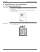

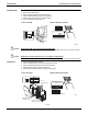
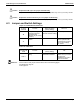
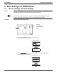
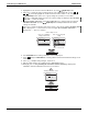

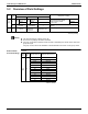
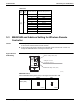
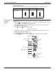
Table Of Contents

SiUS091601EA Field Settings for FTX, FVXS Series
Part 7 Trial Operation and Field Settings 208
Caution
Caution
FTX18/24UVJU 1. Remove the front grille.
2. Remove the electrical box.
3. Remove the shield plate of the electrical box.
4. Cut the address setting jumper JA on the PCB.
5. Remove the cover of remote controller battery.
6. Cut the address setting jumper J4.
Replace the PCB if you cut a jumper unintentionally.
Jumpers are necessary for electronic circuit. Improper operation may occur if you cut any of them.
Replace the remote controller if you cut a jumper unintentionally
.
Jumpers are necessary for electronic circuit. Improper operation may occur if you cut any of them.
FVXS Series 1. Remove the electrical wiring box.
2. Cut the address jumper (JA) on the printed circuit board.
3. Cut the address jumper (J4) in the remote controller.
4. Attach the electrical wiring box as they were.
5. Attach the front panel and the front grille as they were.
Indoor unit PCB Wireless Remote Controller
R7000284
(R9665)
ADDRESS
JC
JA
JB
ADDRESS:JA
EXIST
1
CUT
2
ADDRESS
EXIST
1
CUT
2
Jumper (J4)
Do not cut the left jumper.
Indoor Unit PCB Wireless Remote Controller
R7000286
Sensor
securing plate
JA
JA
EXIST
CUT
Address
1
2
Side electrical
wiring box cover
Front electrical
wiring box cover
(R18416)
ADDRESS
EXIST
1
CUT
2
Jumper (J4)
∗ Do not cut the left jumper.