
Service Manual
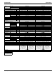
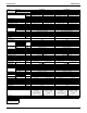

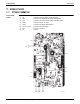
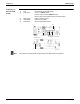
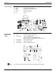
Table Of Contents

Indoor Unit SiUS091601EA
25 Part 3 Printed Circuit Board Connector Wiring Diagram
Note
Filter PCB (PCB1)
Display/Signal
Receiver PCB
(PCB3)
The symbols in the parenthesis are the names on the appropriate wiring diagram.
1) S100 Connector for terminal strip
2) S800 Connector for control PCB (PCB2)
3) FG, HE Connector for ground
4) FU1 Fuse (3.15 A, 250 V)
5) V2 Varistor
3P380932-1
FG
S800
V2 HE S100
FU1
1) S27 Connector for control PCB (PCB2)
2) SW1 (S1W) Indoor unit ON/OFF switch
(Forced cooling operation ON/OFF switch)
Refer to page 199 for details of forced cooling operation.
3) LED1 (H1P) LED for operation (green)
4) LED2 (H2P) LED for timer (yellow)
5) RTH1 (R1T) Room temperature thermistor
S27
SW1 LED2 LED1
RTH1
3P185701-4
(Solder side)
# LED3 is not mounted.