
Service Manual
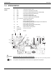
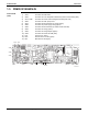
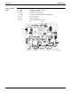
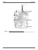
Table Of Contents

SiUS091601EA Indoor Unit
Part 3 Printed Circuit Board Connector Wiring Diagram 28
Caution
Note
1.4 FVXS09/12/15NVJU
Control PCB
(PCB2)
Replace the PCB if you cut a jumper unintentionally.
Jumpers are necessary for electronic circuit. Improper operation may occur if you cut any of them.
The symbols in the parenthesis are the names on the appropriate wiring diagram.
1) S1 Connector for DC fan motor
2) S21 Connector for centralized control (HA)
3) S26 Connector for service PCB (PCB3)
4) S32 Indoor heat exchanger thermistor (R2T)
5) S41 Connector for lower air outlet motor
6) S42 Connector for swing motor
7) S46 Connector for display/signal receiver PCB (PCB4)
8) S48 Connector for sensor PCB (PCB1)
9) H1, H2, H3 Connector for terminal strip
10) E1 Terminal for ground wire
11) JA Address setting jumper
Refer to page 207 for details.
12) JB Fan speed setting when compressor stops for thermostat OFF
Refer to page 209 for details.
13) JC Power failure recovery function
Refer to page 209 for details.
14) FU1 (F1U),
FU2 (F2U)
Fuse (3.15 A, 250 V)
15) LED A LED for service monitor (green)
16) V1, V2 Varistor
E1
V1
H2
H3
FU1 H1 S1 LED A S21 S41 S42 S26
S46
S48
JC
JA
JB
FU2
S32
V2
2P383711-1