
Service Manual
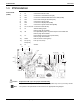
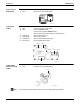
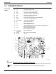
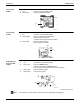
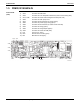
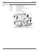
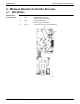
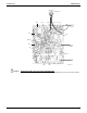
Table Of Contents

Indoor Unit SiUS091601EA
29 Part 3 Printed Circuit Board Connector Wiring Diagram
Note
Sensor PCB
(PCB1)
Service PCB
(PCB3)
Display/Signal
Receiver PCB
(PCB4)
LED3 does not function.
The symbols in the parenthesis are the names on the appropriate wiring diagram.
1) S49 Connector for control PCB (PCB2)
2) RTH2 (R1T) Room temperature thermistor
S49
RTH2
3P191450-1
1) S27 Connector for control PCB (PCB2)
2) SW2 (S2W)-4 Switch for upward airflow limit setting
Refer to page 209 for details.
Keep the other switches as factory setting.
3) SW4 (S4W) Switch for airflow selection
Refer to page 46 for details.
S27
SW4
SW2-4
3P191448-1
1) S47 Connector for control PCB (PCB2)
2) SW1 (S1W) Indoor unit ON/OFF switch
(Forced cooling operation ON/OFF switch)
Refer to page 199 for details of forced cooling operation.
3) LED1 (H1P) LED for operation (green)
4) LED2 (H2P) LED for timer (yellow)
S47SW1LED2
LED1
3P191447-1