00_CV_3P207973-1D.
Shinri Sada Manager Quality Control Department 11th. of Sep. 2009 Low Voltage 2006/95/EC Electromagnetic Compatibility 2004/108/EC * FTX20GV1B, FTX25GV1B, FTX35GV1B, FTK20GV1B, FTK25GV1B, FTK35GV1B, FTX20JV1B, FTX25JV1B, FTX35JV1B DAIKIN INDUSTRIES, LTD. Umeda Center Bldg., 2-4-12, Nakazaki-Nishi, Kita-ku, Osaka, 530-8323 Japan 74736-KRQ/EMC97-4957 KEMA Quality B.V. DAIKIN.TCF.015 M12/09-2009 3SB64526-1D.
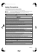
01_EN_3P207973-1D.fm Page 1 Friday, September 4, 2009 10:44 AM Safety Precautions • Read these Safety Precautions carefully to ensure correct installation. • This manual classifies the precautions into WARNING and CAUTION. Be sure to follow all the precautions below: they are all important for ensuring safety. WARNING...............Failure to follow any of WARNING is likely to result in such grave consequences as death or serious injury. CAUTION...............
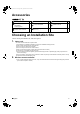
01_EN_3P207973-1D.fm Page 2 Friday, September 4, 2009 10:44 AM Accessories A – L , A Mounting plate 1 E Remote controller holder 1 K Operation manual 1 B Titanium Apatite Photocatalytic Air-Purifying Filter 2 G AAA dry-cell batteries 2 L Installation manual 1 D Wireless remote controller 1 H Indoor unit fixing screws (M4 × 12L) 2 Choosing an Installation Site • Before choosing the installation site, obtain user approval. 1. Indoor unit.
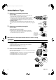
01_EN_3P207973-1D.fm Page 3 Friday, September 4, 2009 10:44 AM Installation Tips 1. Removing and installing front panel. • Removal method 1) Place your fingers in the indentations on the main unit (one each on the left and right sides), and open the panel until it stops. 2) Continue to open the front panel further while sliding the panel to the right and pulling it toward you in order to disengage the rotating shaft on the left side.
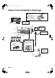
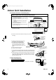
01_EN_3P207973-1D.fm Page 4 Friday, September 4, 2009 10:44 AM Indoor Unit Installation Drawings How to attach the indoor unit. Hook the claws of the bottom frame to the mounting plate. If the claws are difficult to hook, remove the front grille. How to remove the indoor unit. Push up the marked area (at the lower part of the front grille) to release the claws. If it is difficult to Front grille release, remove the front grille.
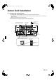
01_EN_3P207973-1D.fm Page 5 Friday, September 4, 2009 10:44 AM Indoor Unit Installation 1. Installing the mounting plate. • The mounting plate should be installed on a wall which can support the weight of the indoor unit. 1) Temporarily secure the mounting plate to the wall, make sure that the panel is completely level, and mark the boring points on the wall. 2) Secure the mounting plate to the wall with screws.
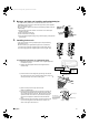
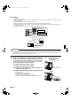
01_EN_3P207973-1D.fm Page 6 Friday, September 4, 2009 10:44 AM 2. Boring a wall hole and installing wall embedded pipe. • For walls containing metal frame or metal board, be sure to use a wall embedded pipe and wall cover in the feed-through hole to prevent possible heat, electrical shock, or fire. • Be sure to caulk the gaps around the pipes with caulking material to prevent water leakage. 1) Bore a feed-through hole of 65mm in the wall so it has a down slope toward the outside.
01_EN_3P207973-1D.fm Page 7 Friday, September 4, 2009 10:44 AM Indoor Unit Installation 3-2. Left-side, left-back, or left-bottom piping. How to replace the drain plug and drain hose. Drain hose attachment position • Replacing onto the left side 1) Remove the insulation fixing screws on the right to remove the drain hose. 2) Reattach the insulation fixing screw on the right as it was. * (Forgetting to attach this may cause water leakages.
01_EN_3P207973-1D.fm Page 8 Friday, September 4, 2009 10:44 AM 4. Wiring. 1) Strip wire ends (15mm). 2) Match wire colours with terminal numbers on indoor and outdoor unit’s terminal blocks and firmly screw wires to the corresponding terminals. 3) Connect the earth wires to the corresponding terminals. 4) Pull wires to make sure that they are securely latched up, then retain wires with wire retainer. 5) In case of connecting to an adapter system. Run the remote control cable and attach the S21.
01_EN_3P207973-1D.fm Page 9 Friday, September 4, 2009 10:44 AM Indoor Unit Installation 5-5. Prepare the accessory (separate product) [Figure 2]. 1) Remove the cover from the accessory (separate product). 2) Insert the connection cord into connector “S21” (white) in the accessory (separate product). 3) Route each of the connection cords through the cut-outs in the accessory, then reinstall the accessory cover in its original position.
01_EN_3P207973-1D.fm Page 10 Friday, September 4, 2009 10:44 AM 6. Drain piping. The drain hose should be inclined downward. 1) Connect the drain hose, as described right. No trap is permitted. Do not put the end of the hose in water. 2) Remove the air filters and pour some water into the drain pan to check the water flows smoothly. 3) If drain hose extension or embedded drain piping is required, use appropriate parts that match the hose front end.
01_EN_3P207973-1D.fm Page 11 Friday, September 4, 2009 10:44 AM Refrigerant Piping Work 2. Refrigerant piping. CAUTION 1) Use the flare nut fixed to the main unit. (To prevent cracking of the flare nut by aged deterioration.) 2) To prevent gas leakage, apply refrigeration oil only to the inner surface of the flare. (Use refrigeration oil for R410A.) 3) Use torque wrenches when tightening the flare nuts to prevent damage to the flare nuts and gas leakage.
01_EN_3P207973-1D.fm Page 12 Friday, September 4, 2009 10:44 AM Trial Operation and Testing 1. Trial operation and testing. 1-1 Measure the supply voltage and make sure that it falls in the specified range. 1-2 Trial operation should be carried out in either cooling or heating mode. • In cooling mode, select the lowest programmable temperature; in heating mode, select the highest programmable temperature. 1) Trial operation may be disabled in either mode depending on the room temperature.
00_CV_3P207973-1D.fm Page 2 Friday, September 4, 2009 10:41 AM Two-dimensional bar code is a code for manufacturing.