
Brochure


NV SERIES
PRODUCT SPECIFICATIONS
SYSTEM PERFORMANCE
Model
2.5 Tons 3.0 Tons
Indoor (Cooling Only and Heat Pump)
FTX30NVJU FTX36NVJU
Outdoor (Cooling Only)
RK30NMVJU RK36NMVJU
Outdoor (Heat Pump)
RX30NMVJU RX36NMVJU
Cooling Capacity (Rated) Btu/h 31,400 34,400
Cooling Capacity (Min. - Max.) Btu/h 10,200 - 31,400 10,200 ~ 33,200 - 34,400
Heating Capacity (Rated) Btu/h 34,800 36,000
Heating Capacity (Min. - Max.) Btu/h 10,200 - 34,800 10,200 ~ 35,200 - 36,000
SEER 17.5 15.9
EER 9.85 9.1
HSPF
+
9.3 9.2
Piping Connections
Liquid
in. (mm)
Ø 1/4 (Ø 6.4) Ø 1/4 (Ø 6.4)
Gas Ø 5/8 (Ø 15.9) Ø 5/8 (Ø 15.9)
Condensate Drain Ø 5/8 (Ø 15.9) Ø 5/8 (Ø 15.9)
Max. Interunit Piping Length
ft. (m)
98-3/8 (29.8)
Max Interunit Piping Height 65-5/8 (20)
Chargeless 32-13/16 (9.8)
Amount of Additional Charge of Refrigerant oz./ft (g/m) 0.32 (30)
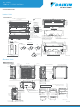
Indoor Dimensions (H × W × D) in. (mm)
13-3/8 x 47-1/4 x 10-3/16
(350 x 1200 x 259)
Outdoor Dimensions (H × W × D) in. (mm)
28-15/16 x 34-1/4 x 12-5/8
(729 x 870 x 320)
Operating Range - Cooling - RX/RK Standard °F DB (°C) 50 - 115 (10 - 46)
Operating Range - Cooling - RX/RK Enhanced* °F DB (°C) 14 - 115 (-10 - 46)
Operating Range - Cooling - RX/RK Low Ambient** °F DB (°C) -4 - 115 (-20 - 46)
Operating Range - Cooling - RK Only - Ultra Low Ambient*** °F DB (°C) -22 - 115 (-30 - 46)
Operation Range - Heating
+
°F WB (°C) 5 - 65 (-15 - 18)
Unit Combination Power Supply Compressor OFM IFM
Indoor Unit Outdoor Unit Hz - Volts Voltage Range MCA MOP RLA W FLA W FLA
FTX30NVJU RK30NMVJU
60 - 208
Min. 187 V Max. 253 V 17 20 16.25 93 0.62 64 0.37
60 - 230
FTX36NVJU RK36NMVJU
60 - 208
Min. 187 V Max. 253 V 17 20 16.25 123 0.83 64 0.37
60 - 230
FTX30NVJU RX30NMVJU
60 - 208
Min. 187 V Max. 253 V 19.8 20 18.25 93 0.62 64 0.37
60 - 230
FTX36NVJU RX36NMVJU
60 - 208
Min. 187 V Max. 253 V 19.8 20 18.25 123 0.83 64 0.37
60 - 230
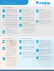
RK30/36NMVJU and
RX30/36NMVJU
STANDARD OPERATION LIMITS
RK30/36NMVJU
* Activated with a dipswitch setting. Refer to installation manual for more details.
** Activated with a dipswitch setting and use of air direction adjustment grille (KPW063A4). Refer to installation manual for more details.
*** Activated with additional dipswitch setting and notes per **. Refer to installation manual for more details.
+
Applicable to heat pump models only.
Notes:
1. The graphs are based on the following conditions:
• Equivalent piping length 25 ft.
• Level difference 0 ft.
• Air flow rate High
2. Facility setting (cooling at low outdoor temperature):
• This function is limited only for facilities
(the target of air conditioning is equipment such as computer)
• Never use it in a residence or office (the space where there is a human)
• Refer to the installation manual in detail of setting
Indoor Unit Optional Accessories Outdoor Unit Optional Accessories
BRC944B2 Wired Remote Controller (Requires 1 cord below) KPW063A4 Air Direction Adjustment Grille
BRCW901A03 Wired Remote Controller Cord (Shielded wire) 9.8 ft KKG063A42 Back Protection Wire Net
BRCW901A08 Wired Remote Controller Cord (Shielded wire) 26.3 ft KKP937A4 Drain Plug - Standard
BRP072A43 Wireless LAN connection Adaptor KEH063A4E Drain Pan Heater
KAF970A48 Titanium Apatite Deodorizing Filter (Without frame) Standard KPS063A41 Snow Hood (Intake side panel)
KKF910AA4 Remote Controller Loss Prevention with Chain KPS063A44 Snow Hood (Intake side panel)
KPS063A47 Snow Hood (Outlet)