
Installation manual

Addendum IM 1152 — MT158
IM 1016-1/ Page 1 of 3 © 2010 McQuay International 800-432-1342 www.mcquay.com
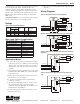
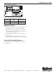
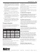
Figure 1: Wiring Diagram for 3-Wire Valve Configuration
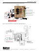
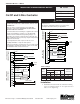
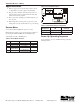
Figure 2: Wiring Diagram for On/Off Ouput Configuration
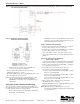
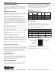
Table 1: Ratings
Installation
1 Install the thermostat with the two furnished mounting
screws to a standard 4-11/16" x 2-1/8" square device box
with a 2" x 4" adapter ring.
Installation and Maintenance Manual IM 1016-1
MTB 158 Microprocessor Thermostat
On/Off and 3-Wire Controller
Group: Applied Air Systems
Part Number: 910102991
Date: November 2010
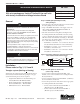
DANGER
READ THESE INSTRUCTIONS CAREFULLY BEFORE
ATTEMPTING TO INSTALL, OPERATE OR SERVICE THIS
THERMOSTAT.
Failure to observe safety information and comply with
instructions could result in PERSONAL INJURY, DEATH
AND/ OR PROPERTY DAMAGE.
To avoid electrical shock or damage to equipment, disconnect
power before installing or servicing. Use only wiring with
insulation rated for full thermostat operating voltage. Use
copper wire only. Insulate or wirenut all un-used leads. Any
wiring, including the remote probe,may carry the full operating
voltage of the thermostat.
To avoid potential fire and/ or explosion do not use in
potentially flammable or explosive atmospheres.
Retain these instructions for future reference. You must review
your application and national and local codes to ensure that
your installation will be functional and safe.
LOW VOLTAGE
CONNE C TIONS
LINE VOLTAGE
CONNE C TIONS
L1 (HOT)
LO
MED
24 VAC 1
24 VAC 2
SETBACK INPUT
MAIN 1 OPEN
SEC 1 OPEN
MAIN 2 CLOSE
SEC 2 CLOSE
REMOTE PROBE
PIPE SENSOR
FAN
L2 OR NEUTRAL
24 VAC
XFMR
MAIN
SECONDARY
OUTSIDE AIR
DAMPER OUTPUT
10
11
12
13
14
15
16
17
1
2
3
4
5
6
7
HIGH
OR SINGLE SPEED FAN
CAUTION
Care should be used to avoid electrostatic discharge to the
microprocessor.
This unit has configuration jumpers. You may need to
reconfigure this thermostat for your application.
Voltage
Rating
Fan and system switches
Thermostatic
Switching
(Pilot Duty)
Inductive
Resistive
Amps
Pilot
Duty
FLA LRA
24 VAC N.A. N.A. N.A. 24 VA 10 VA
120 VAC 5.8 34.8 6.0 125 VA NA
240 VAC 2.9 17.4 5.0 125 VA NA
277 VAC 2.4 14.4 4.2 125 VA NA
LOW VOLTAGE
CONNECTIONS
LINE VOLTAGE
CONNECTIONS
FAN
L2 OR NEUTRAL
REMOTE PROBE
PIPE SENSOR
L1 (HOT)
LO
MED
HIGH
OR SINGLE SPEED FAN
24 VAC 1
24 VAC 2
SETBACK INPUT
FAN
24 VAC
XFMR
MAIN 1
SEC 1
HEAT 2
MAIN 1
OUTPUT
SECONDARY
1 OUTPUT
DEMAND
OUTPUT
2ND STAGE
HEAT
OUTSIDE AIR
DAMPER OUTPUT
10
11
12
13
14
15
16
17
1
2
3
4
5
6
7