Installation & Maintenance Data IM 1193 Group: PTAC Part Number: 910140864 Date: October 2013 Packaged Terminal Air Conditioner 16" x 42" PGAN with Top-Mounted Hydronic Heat Note: Installation and maintenance are to be performed only by qualified personnel who are familiar with local codes and regulations and are experienced with this type of equipment. Caution: Sharp edges and coil surfaces are potential injury hazards. This manual must be left with the owner of the equipment.
Contents Safety Information................................................................3 Inspection..............................................................................3 Daikin Model PGAN Product Nomenclature......................4 Unit Dimensions...................................................................5 Wall Opening Requirements................................................6 Installing Louver Frame.......................................................
Safety Information Inspection Follow all safety codes. Wear safety glasses and work gloves. Use a quenching cloth for brazing operations. Have a fire extinguisher available. Follow all warnings and cautions in these instructions and attached to the unit. Consult applicable local building codes and National Electrical Codes (NEC) for special requirements. Recognize safety information. When you see a safety symbol on the unit or in these instructions, be alert to the potential for personal injury.
Daikin Model PGAN Product Nomenclature Note: For Illustration purposes only. Not all options available with all models. P GAN 1 009 E D A AY YYYYY LB SYY B Unit Type L Warranty P = PTAC A = Standard C = 4 Yr Extnd. Comp. L = 4 Yr Extnd. Refrig.
Unit Dimensions Table 1: Cabinet & wall sleeve dimensions 1¼" Recess for Architectural Louver "A" Room Cabinet "D" Wall Sleeve "B" Wall Thickness 18¾" 17¾" 16¾" 15¾" 14¾" 13¾" 12¾" 11¾" 10¾" 10¾" 10¾" 10¾" 10¾" 13¾" 13¾" 13¾" 13¾" 13¾" 13¾" 13¾" 13¾" 13¾" 14¾" 15¾" 16¾" 17¾" 4¾–5¾" 5¾–6¾" 6¾–7¾" 7¾–8¾" 8¾–9¾" 9¾–10¾" 10¾–11¾" 11¾–12¾" 12¾–13¾" 13¾–14¾" 14¾–15¾" 15¾–16¾" 16¾–17¾" Standard Size Wall Sleeve Note: Electrical rough-in should be located behind kickplate (removable front) and below wall sl
Figure 2: Louver frame dimensions WARNING Residential and institutional cleaning compounds can cause permanent damage to the packaged terminal unit. To avoid damage to unit controls and heat transfer surfaces, do not spray cleaning compounds onto the discharge grille, return air opening, or unit controls. Normal cleaning can be accomplished by wiping the unit surface with a damp cloth.
Wall Construction Types CAUTION Figure 4: Panel wall (thin) construction Do not drill holes in the base of the wall sleeve. Use shims between the wall and the wall sleeve to prevent wall sleeve distortion during anchoring. Steel Studs Note: Concrete Pillars When using recessed louver wall sleeve, level and plumb wall sleeve using the top and sides of the sleeve and the chassis slide rails. DO NOT level using the bottom of the wall sleeve as it has a built in pitch to drain. Installing Louvers 1.
Applications utilizing field supplied louvers require additional considerations: 1. Louvers supplied by others must have 70% free area or a pressure drop not exceeding 0.05 in. w.g. (12.45 Pa) at 300 fpm (1.524 m/sec) face velocity, and a blade design that will not cause recirculation of air. 2. Daikin does not warrant the rain and water leakage resistance of its equipment when used with louvers by others. 3. All louvers by others must be approved by Daikin engineering prior to installation.
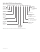
Figure 9: 16" x 42" optional recessed louver wall sleeve with continuous flange and drip edge X* Flange location (from outdoor side of sleeve) is factory provided in increments of 1/8" D** 42" Flange Height (Standard = 1-1/4") 16" Louver Mounting Holes Drip Edge Notes: 1. Caulk entire perimeter of wall sleeve after installation. 2. Seal area between louver and wall sleeve to prevent condenser air recirculation. ** See "Table 1: Cabinet & wall sleeve dimensions" on page 5 for dimension "D".
Thick Wall Construction A heavy-gauge, corrosion resistant wall sleeve is provided for each unit. The wall sleeve is either shipped in a separate carton or shipped in a multi-pack of 15. Typical installation for masonry walls is shown in Figure 11. The recommended installation procedure for this type of construction is as follows: 1. Clean the opening of all debris that may interfere with installation. 2. Be sure the unit’s center of gravity falls within the load bearing surface of the wall.
Figure 13: Anchoring the wall sleeve Anchoring The Wall Sleeve 7. Anchoring the wall sleeve is accomplished as shown in Figure 13. Use the rubber isolation washers with the fasteners to minimize sound transmission from the equipment to the wall, at the point of contact. A 5⁄16" (8mm) hole is provided on each side, 2" (51mm) down from the top and 2" (51mm) in from the rear of the wall sleeve. It may be necessary to drill additional holes in the wall sleeve to firmly secure it.
Figure 15: Attach hydronic heat section to wall sleeve Hydronic Heat Section Wall Sleeve square holes Heat section hooks Piping Recommended Piping Detail (Field-Installed) Figure 16: Typical hot water coil piping Figure 17: Typical steam coil piping Coil Coil Side View Air Vent Balancing Valve Automatic Valve Side View Automatic Valve Steam Trap Gate Valve Gate Valve Plug to (Control Box) Plug to (Control Box) Gate Valve Return Supply IM 1193 / Page 12 of 32 Supply Gate Valve Return
Installing The Valve Prior to soldering the normally closed two-way valve, open the ports by slowly moving the manual operating lever to the retaining notch until lever is secured by valve spring. The lever will reset to the automatic position the first time the valve is energized. Note: When installing two-way valves, the flow direction is from end “B” as shown in Figure 18. Figure 18: 2-way valve installation Valve Wire Harness Motor * N.O. YL N.C. BL Note: 1.
Supply and Return Coil Arrangements Steam Hot Water Figure 20: Left-hand supply and return Figure 24: Left-hand supply and return Return Supply Supply Return Figure 25: Right-hand supply and return Figure 21: Right-hand supply and return Return Supply Supply Return Figure 26: Left-hand supply, right-hand return or Righthand supply, left-hand return Figure 22: Right-hand supply, left-hand return Supply Return or Supply Return Figure 23: Left-hand supply, right-hand return Supply Return IM
Installing Cooling Chassis Correct installation of the cooling chassis is extremely important to insure the proper operation of the unit. Install the chassis as follows: 11. Slide chassis into wall sleeve until firmly seated against weather seals of wall sleeve. Figure 28: Slide chassis into wall sleeve CAUTION Do not pull on evaporator fan housing, control box or compressor. Do not lift by pulling on the tubing. Tubing can crack or bend damaging the unit. 1. 2. 3. 4. 5. 6.
Table 13: Voltage measurements Installing The Touchpad Control Operating Voltage Unit Voltage Figure 31: Touchpad installation Voltage Utilization Range Rating Minimum Maximum 230/208 197 253 265 238 292 115 103.5 126.5 Touchpad Controller Note: The use of extension cords to increase the length of the plug/cord set is not recommended. The attachment plug size should be used to determine the circuit ampacity and overcurrent protection.
Unit-Mounted Controller & Remote Thermostats Non-Programmable Electronic Thermostat (P/N 910140678) Programmable Electronic Thermostat (P/N 910140679) Non-Programmable, Auto Changeover, Fan Speed Control, Hardwired 7-Day Programmable, Auto Changeover, Fan Speed Control, Hardwired ■ ■ ■ ■ ■ ■ ■ ■ ■ ■ ■ ■ ■ 7-Day Programmable Single Stage Heat Pump/Non-Heat Pump Systems Backlit Display Single Stage Heat/Cool Systems Field Calibration Auto Changeover Button Lockout Function Two Speed Fan Control SimpleSe
Operating Instructions Cooling or Heating – Manual Operation The PGAN unit controller has built-in features such as random start, compressor time delay, night setback, load shed, shutdown. The 24 volt low voltage terminal strip is set so R-G energizes the fan. R-W1 energizes the fan and compressor. User Controls A 4 button touch key pad, with a High/Low Fan speed and Auto/On Switch located behind the control door, controls both temperature and operation mode.
Figure 33: Internal Control Board - Remote Control Terminations AUXILIARY DS1 DS2 MS1 MS2 EH IN REMOTE THERMOSTAT LS FD1 FD2 TF- TF+ C R GL W2 Y/W1 B GH Simple to operate, single push button for one-stage heating and cooling, or single stage heat pump. Zone compatible and 4- or 5 wire compatible (terminal “C” is optional for nonheat pump systems). System “heat-off-cool” switch and fan “on-off” switch.
Standard Auto or Manual-Changeover Two-Stage Heat/ Two-Stage Cool Specs Configuration Settings for Internal Control Touchpad Part No.
Table 15: Internal control touchpad configuration settings Configuration Code C1 C2 Description Interface Fan Operation Option Code Description 0* Chassis Membrane rE Wireless Remote L5 Wired Thermostat bP Button present bA* 7-button, reverts to cyclic A Always run fan (even in Off) bC 7-button, reverts to continuous C Cooler Only C3 Reverse Cycle Operation H* Heat Pump* 0 Service No Operation "Eo" C4 Room I.D. Digit 1 & 2 00* - 99 00* - 99 C5 Room I.D.
Diagnostic Maintenance & Status Report - Internal Control Touchpad The Diagnostic Maintenance & Status Report on the Internal Control Touchpad provides detailed information on PTAC control operation and operational status including present modes, failures, airflow restriction warnings, operating temperatures, and past failures. The lower right hand dot on the center display flashes in this mode.
Table 16: Diagnostic codes Code Status Display Error Light Suggested Action Modes FP Freeze Protection Engaged. The room temperature measured by the wireless remote thermostat or indoor ambient thermistor active sensor falls below 40°F. Y N No Action required. This setting will disengage when the room temperature rises above 43°F. Fd Front Desk switch is closed. All outputs are switched off. Y N Open front desk switch to allow occupant unit operation.
Monthly Maintenance and Cleaning Intake Air Filters To properly maintain the operational performance of your PTAC unit, it is extremely important that the inlet air filters be cleaned once per month or more often if operated in dusty or dirty locations or conditions. The intake air filters are constructed of durable polypropylene. The “air intake” air filters can be easily inserted into the cabinet front using the cabinet filter guides.
PTAC/PTHP Startup Report–Audit Job Name __________________________________________ City ________________G.O. # ____________ Installer __________________________________________________________________Total No.
Troubleshooting Trouble 1. 2. Blowers won’t operate on cool Blowers operate on cool but compressor does not start Cause Cure a. No power a. b. c. Faulty touchpad/thermostat. Loose connections at push-button switch. b. c Check supply line fusses, circuit breakers, and be sure the power is on. Blown fuses would indicate circuit overloading, a short circuit, or a ground condition in the circuit Voltage supply to the equipment should be checked.
Trouble 9. Too much cooling. Cause Cure a. b. Thermostat set too low. Defective thermostat a. b. Adjust. Replace. a. Condensate drain from evaporator to condenser plugged. Insulating seals on equipment damaged. Evaporator blower motor not up to speed. Evaporator blower incorrectly positioned. a. Remove obstructions to water flow. b. c. d. b. c. d. Adjust or replace. Check for correct voltage. Replace motor if necessary. Tighten. 11. Blowers won’t operate on Heat. a. b. c. d. e. f. No power.
Wiring Diagrams PGAN with Hydronic Heat BK BK 7 LINE 2 LINE 1 HEATER 1 HEATER 2 BK RD COMPRESSOR BK BL RD BK R RD 7 RS 485 COM TO MOTOR GND 230/265 VSTM OD FAN HIGH FAN LOW REV VALVE HIGH VOLTAGE! DISCONNECT ALL POWER BEFORE SERVICING OR INSTALLING THIS UNIT. MULTIPLE POWER SOURCES MAY BE PRESENT. FAILURE TO DO SO MAY CAUSE PROPERTY DAMAGE, PERSONAL INJURY OR DEATH.
Wiring Diagram PGAN with Hydronic Heat, Power Vent and Power Door OR LINE 1 HEATER 1 HEATER 2 LINE 2 COMPRESSOR R VSTM OD RS485 COM 230/265 GND TO MOTOR FAN HIGH FAN LOW PK RD REV VALVE RD PK 6 PK VT GY BR HIGH VOLTAGE! DISCONNECT ALL POWER BEFORE SERVICING OR INSTALLING THIS UNIT. MULTIPLE POWER SOURCES MAY BE PRESENT. FAILURE TO DO SO MAY CAUSE PROPERTY DAMAGE, PERSONAL INJURY OR DEATH.
Wiring Diagram PGAN with Hydronic Heat, Variable Speed Condenser and Evaporator Fan Motors FAN HIGH BK COMPRESSOR WH RD RD LINE 1 HEATER 1 HEATER 2 BK LINE 2 WH VT BK BK 1650 1500 1350 1170 RS485 COM TO MOTOR 230/265 VSTM OD GND VSM CM FAN MOTOR WH BK RD VSTM ID RS485 COM 230/265 GND VSM EM EVAP MOTOR TO MOTOR FAN LOW REV VALVE HIGH VOLTAGE! DISCONNECT ALL POWER BEFORE SERVICING OR INSTALLING THIS UNIT. MULTIPLE POWER SOURCES MAY BE PRESENT.
Wiring Diagram PGAN with Hydronic Heat, Variable Speed Condenser, Evaporator Fan Motors, Power Vent and Door Option OR RS485 LINE 1 HEATER 1 HEATER 2 LINE 2 COMPRESSOR COM RS485 230/265 VSTM OD COM TO MOTOR 230/265 VSTM ID GND VSM CM FAN MOTOR WH GND VSM EM EVAP MOTOR TO MOTOR FAN HIGH WH FAN LOW PK RD REV VALVE RD PK 6 PK VT GY BR HIGH VOLTAGE! DISCONNECT ALL POWER BEFORE SERVICING OR INSTALLING THIS UNIT. MULTIPLE POWER SOURCES MAY BE PRESENT.
Daikin Training and Development Now that you have made an investment in modern, efficient Daikin equipment, its care should be a high priority. For training information on all Daikin HVAC products, please visit us at www.DaikinAP.com and click on training, or call 540-248-9646 and ask for the Training Department. Warranty All Daikin equipment is sold pursuant to its standard terms and conditions of sale, including Limited Product Warranty. Consult your local Daikin Representative for warranty details.