Catalog 1304-1 Packaged Terminal Air Conditioner with Top-Mounted Hydronic Heat Model PGAN - Unit Sizes 007 – 015 Engineered for flexibility and performance™
Contents Daikin Model PGAN Product Nomenclature.............. 3 16" × 42" Model PGAN with Top-Mounted Hydronic Heat................................................................................ 4 Introduction.............................................................. 4 Years of Experience Matter...................................... 4 The Hydronic Experts.............................................. 4 Controls With Built-In Hydronic Logic...................... 4 Quiet Comfort..........................
Daikin Model PGAN Product Nomenclature Note: For Illustration purposes only. Not all options available with all models. P GAN 1 009 E D A AY YYYYY LB SYY B Unit Type L Warranty P = PTAC A = Standard C = 4 Yr Extnd. Comp. L = 4 Yr Extnd. Refrig.
16" × 42" Model PGAN with Top-Mounted Hydronic Heat Introduction Years of Experience Matter As the world’s largest heating, ventilation and air-conditioning manufacturer, Daikin stands behind its product with the strength of a global organization. With Daikin representation and quality U.S. manufactured products; we continue to provide fast delivery and hands-on support that you’ve come to expect to make your project a success.
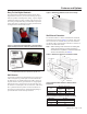
More For Your Investment 1 Cooling PGAN Chassis 4 Room Cabinet • • • • • • • • Energy efficient design with two speed condenser motor, rotary compressor and quiet two speed indoor tangential fan Filter drier to protect the compressor and lengthen the life of the unit 100% run tested, and leak-tested during the manufacturing process, and again prior to shipment Indoor air quality (IAQ) fresh air damper (manual or automatic) and cleanable filter Optional sound reduction and seacoast package 64" LCDI saf
AHRI Performance Data Table 1: AHRI Performance Data(5) Cooling Model 007 009 012 015 BTUH 7200 7600 7600 9000 9000 8800 11700 11700 14000 14000 Sensible BTUH 5300 5700 5700 6000 6000 5900 7800 7800 9400 9400 EER 11.7 11.5 11.5 11.1 11.1 11.1 10.3 10.3 9.6 9.6 Volts 115 230/208 265 115 230/208 265 230/208 265 230/208 265 FLA 7.5 4.1 3.6 8.9 4.7 4.2 6.2 5.4 7.3 6.
Features and Options Easy To Use Digital Controls Figure 2: Wall Sleeve with Recessed Louver Design The optional non-programmable touchpad control offers digital readout and is easy to use when selecting fan speed, mode of operation and temperature setting. A precise digital temperature display provides occupants with an exact comfort setting, thereby eliminating uncomfortable temperature swings and costly overheating/overcooling associated with non-digital electro-mechanical controls.
Features and Options Louver Frame Manual Fresh Air Damper Control Louver frames are used for panel wall and thin wall applications to assure positive anchoring to the wall. The wall sleeve is installed flush with the outside of the building. The louver frame is placed around the wall sleeve. Outdoor fresh air is brought in through a manual damper door, using the control lever, hidden from the occupant's view to allow you to manage ventilation requirements.
Features and Options Positive Condensate Removal Figure 10: Sloped Basepan & Plastic Drain Pan Removable Condenser Fan Motor Allows easy access to enable regular cleaning of coils, which is essential to maintain unit efficiency and protect the compressor for long unit life. Plastic Drain Pan Base Pan Humidity controls and positive condensate removal features together greatly reduce or eliminate excess condensate.
Unit-Mounted Control Optional Programmable Electronic Thermostat Optional Non-Programmable Electronic Thermostat (P/N 910140679) (P/N 910140678) 7-Day Programmable, Auto Changeover, Fan Speed Control, Hardwired Non-Programmable, Auto Changeover, Fan Speed Control, Hardwired ■ ■ ■ ■ ■ ■ ■ ■ ■ ■ ■ ■ 7-Day Programmable Backlit Display Single Stage Heat/Cool Systems Field Calibration Auto Changeover Button Lockout Function Two Speed Fan Control SimpleSet™ Programming Remote Temperature Sensor Capability
Unit-Mounted Control Cooling or Heating – Manual Operation The PGAN internal unit controller has built-in features such as random start, compressor time delay, night setback, load shed, shutdown. The 24 volt low voltage terminal strip is set so R-G energizes the fan. R-W1 energizes the fan and compressor. User Controls A 4 button touch key pad, with a High/Low Fan speed and Auto/On Switch located behind the control door, controls both temperature and operation mode.
PGAN Dimensions Figure 13: PGAN Unit Dimensions Programmable Touchpad Controller Note: Electrical rough-in should be located behind kickplate (removable front) and below wall sleeve.
Hydronic Heating Configurations Steam Hot Water Figure 14: Left-hand supply and return Figure 18: Left-hand supply and return Return Supply Supply Return Figure 19: Right-hand supply and return Figure 15: Right-hand supply and return Return Supply Supply Return Figure 20: Left-hand supply, right-hand return or Righthand supply, left-hand return Figure 16: Right-hand supply, left-hand return Supply Return or Supply Return Return or Supply Figure 17: Left-hand supply, right-hand return Note:
Piping Piping Recommended Piping Detail (Field-Installed) Figure 21: Typical Hot Water Coil Piping HFLO Sensor - to be covered with provided insulating cork tape Coil Side View Air Vent Balancing Valve Automatic Valve Gate Valve The minimum cabinet depth is 10.75". This is required because the wall sleeve MUST extend a minimum of 1.625" into the room and 9.125" is required to cover the chassis. This totals 10.75". Standard cabinets range from 10.75" to 18.75" in 1" increments.
Typical Installation Types Standard Wall Sleeve Installation Panel/Window Wall Sleeve Installation Masonry Wall Construction Application Wall Sleeve Depth, Wall Thickness, & Optional Continuous Flange Dimensions Notes: 1. Wall sleeve to extend a minimum of 1-5/8" past finished sheetrock. 2. Wall sleeve should be recessed the thickness of the louver from face of brick so that when louver is installed it is flush with face of building.
Wall-Mounted Thermostats – Quick Selection Guide Table 2: Wall Mounted Thermostats – Quick Selection Guide Thermostat Item Number 910116771 910116772 • • Single Stage Two Stage Heat Pump • • Manual Changeover (Cool/Off/Heat) • • Settable Differential Range • • Auto Changeover Status LEDs Backlit Display • • 7-Day or 5-2 day or 5-1-1 Programmable • Temporary Hold • Programmable Fan On/Off Delay Non-Programmable • Hard Wired • • Wireless 4 or 5 Wire Capable • • Freeze Protection • Fan Swit
Remote Wall-Mounted Thermostats Remote Thermostat Control The Remote Thermostat can be any thermostat that can interface with an electronic thermostat via RCBWYG terminals. The Internal Control Board (ICB) must be configured for C1 and L5, and the thermostat wiring harness connected to the thermostat and remote thermostat pins on the ICB. During a call the remote thermostat will pass R back to the controller on a respective terminal.
Remote Wall-Mounted Thermostats Thermostat Location Non-Programmable Thermostat Specs This unit is designed to be operated with remote wall mounted thermostats. For further information on thermostats approved for use with this unit, contact your sales representative. For best performance results, the thermostat should be located approximately five feet above the floor on a vibration free, inside wall in an area with good air circulation.
Remote Wall-Mounted Thermostats Wall-Mounted, 7, 5-2 & 5-1-1 Programmable Thermostat Specs Standard Auto or Manual-Changeover TwoStage Heat/ Two-Stage Cool Specs Manual Changeover One-Stage Heat and Cool or One-Stage Heat Pump Part No. 910116774 (1-Pk, White with Wall Plate) Part No.
Remote Wall-Mounted Thermostats Optional Remote Sensor Part No. 107096010 (Used in Conjunction with Thermostat Part No. 910116774 Only) The Fast, Easy Solution For Temperature Sensing Problems.
Wiring Diagrams PGAN with Hydronic Heat BK BK 7 LINE 2 LINE 1 HEATER 1 HEATER 2 BK RD COMPRESSOR BK BL RD BK R RD 7 RS 485 COM TO MOTOR GND 230/265 VSTM OD FAN HIGH FAN LOW REV VALVE HIGH VOLTAGE! DISCONNECT ALL POWER BEFORE SERVICING OR INSTALLING THIS UNIT. MULTIPLE POWER SOURCES MAY BE PRESENT. FAILURE TO DO SO MAY CAUSE PROPERTY DAMAGE, PERSONAL INJURY OR DEATH.
Wiring Diagram PGAN with Hydronic Heat, Optional Power Vent and Power Door OR LINE 1 HEATER 1 HEATER 2 LINE 2 COMPRESSOR R VSTM OD RS485 COM 230/265 GND TO MOTOR FAN HIGH FAN LOW PK RD REV VALVE RD PK 6 PK VT GY BR HIGH VOLTAGE! DISCONNECT ALL POWER BEFORE SERVICING OR INSTALLING THIS UNIT. MULTIPLE POWER SOURCES MAY BE PRESENT. FAILURE TO DO SO MAY CAUSE PROPERTY DAMAGE, PERSONAL INJURY OR DEATH.
Wiring Diagram PGAN with Hydronic Heat, Variable Speed Condenser and Evaporator Fan Motors FAN HIGH BK RS485 COMPRESSOR RD RD LINE 1 HEATER 1 HEATER 2 BK LINE 2 WH VT BK WH BK 1650 1500 1350 1170 RS485 COM TO MOTOR 230/265 VSTM OD GND VSM CM FAN MOTOR WH BK RD COM VSTM ID 230/265 GND VSM EM EVAP MOTOR TO MOTOR FAN LOW REV VALVE HIGH VOLTAGE! DISCONNECT ALL POWER BEFORE SERVICING OR INSTALLING THIS UNIT. MULTIPLE POWER SOURCES MAY BE PRESENT.
Wiring Diagram PGAN with Hydronic Heat, Variable Speed Condenser, Evaporator Fan Motors, and Optional Power Vent and Door OR RS485 RS485 LINE 1 HEATER 1 HEATER 2 LINE 2 COMPRESSOR COM 230/265 VSTM OD COM TO MOTOR 230/265 VSTM ID GND VSM CM FAN MOTOR WH GND VSM EM EVAP MOTOR TO MOTOR FAN HIGH WH FAN LOW PK RD REV VALVE RD PK 6 PK VT GY BR HIGH VOLTAGE! DISCONNECT ALL POWER BEFORE SERVICING OR INSTALLING THIS UNIT. MULTIPLE POWER SOURCES MAY BE PRESENT.
Guide Specifications Furnish and install where shown on plans packaged terminal air conditioners of the sizes and capacities shown on the schedule. The units shall be located as shown on the drawings and shall include cabinet/wall sleeve, chassis, outdoor louver, hydronic heat section, valve, and room cabinet. All units shall be ETL listed for safety and AHRI certified for performance. Overall dimensions for the basic unit shall not exceed 52" wide, 22-1/2" high, and 17-3/4" deep.
Guide Specifications The PGAN control module offers the following outputs: 1. Compressor Output 2. Outdoor Fan 3. Indoor Fan Fan cycle or Fan Continuous and Blower Hi or Blower Lo shall be incorporated to allow either continuous or automatic fan cycle operation at the selected fan speed. When choosing automatic fan cycle operation, the fan shall be energized only when the Indoor Fan is operating. 4. Damper Control 5.
Catalog 1304-1 / Page 27 of 28
Daikin Training and Development Now that you have made an investment in modern, efficient Daikin equipment, its care should be a high priority. For training information on all Daikin HVAC products, please visit us at www.daikin.com and click on Training, or call 540-248-9646 and ask for the Training Department. Warranty All Daikin equipment is sold pursuant to its standard terms and conditions of sale, including Limited Product Warranty. Consult your local Daikin Representative for warranty details.