
Operating instructions

Catalog 1304-1 / Page 17 of 28
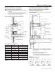
Remote Wall-Mounted Thermostats
Remote Thermostat Control
TheRemoteThermostatcanbeanythermostatthatcaninter-
facewithanelectronicthermostatviaRCBWYGterminals.
TheInternalControlBoard(ICB)mustbeconguredforC1
andL5,andthethermostatwiringharnessconnectedtothe
thermostatandremotethermostatpinsontheICB.During
acalltheremotethermostatwillpassRbacktothecontrol-
leronarespectiveterminal.However,thecontrolpadLED
displaywillindicatethemodeofoperation,andtheroom
temperature.
Notes: In terms of outputs, there are two types of
thermostats: relay contacts and solid state.
If you open the thermostat and don’t see relays then it
must be solid state.
Manufacturers of solid state output thermostats
include loading resistors on their installation kits. They
are of 560 Ohm and 3W value. These resistors are
meant to load thermostat solid state outputs in order
for the output voltage to be either 0 or 24VAC, i.e. no
oating voltage. These resistors are connected from
W, Y, G to common (C), respectively.
Youcanwireanytypeof24Vacthermostatstraightintothe
REMOTET’STATconnectorInternalControlBoard.
Operating Instructions
Cooling or Heating – Manual Operation
ThePGANunitcontrollerhasbuilt-infeaturessuchasran-
domstart,compressortimedelay,nightsetback,loadshed,
shutdown.The24voltlowvoltageterminalstripissetsoR-G
energizesthefan.R-W1energizesthefanandcompressor.
User Controls
A4buttontouchkeypad,withaHigh/LowFanspeedand
Auto/OnSwitchlocatedbehindthecontroldoor,controls
bothtemperatureandoperationmode.
Thermostat Setting
4-buttontouchpadwithdisplay.
PressingtheCOOLthermostatcontrolandtheupordown
arrowswillprovideacoolerroomtemperature.Pressingthe
HEATthermostatcontrolandtheupordownarrowkeyswill
provideawarmerroomtemperature.
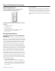
LCDI Power Cord
230/208Vand115VunitsareequippedwithaLCDIpower
cordandcanopentheelectricalcircuittotheunit.Inthe
eventtheunitdoesnotoperate,checktheresetbuttonlocated
onorneartheheadofthepowercordaspartofthenormal
troubleshootingprocedure.
Fan Speed
Thefanspeedselectorswitchwilldeliverhigh,loworauto
fanspeedtocirculateroomair.
Note: The AUTO selection will not be available if a fan speed
is selected without COOL or Heat selection.
FanOperationHIGHorLOWwithHEATorCOOLmode
selected
• Thefanshallrunintheselectedspeed.
• FanOperationAUTOwithHEATorCOOLmodeselected
-Thefanwillruninlowandhighspeed.Thechangesin
fanspeedareautomatic.
Diagnostic Light - Internal Touchpad
Thegreendiagnosticlightlocatedinthelowerlefthand
cornerofthetouchpadandindicatesoperationwarnings.
Thislightusuallyindicatesthateitherthelterorcoilsneed
cleaning.
Master Switch
Themasterswitchdisconnectspowertoallofthesystem
components.Whenthisswitchisintheoffposition,the
compressor,fanmotor,reversingvalve,andelectricresistance
heaterwillallbede-energized.
NOTICE
When using existing thermostats by others;
There are two basic types of thermostats manufactured today;
those with relay contacts, and those with solid-state triacs. If
you open the thermostat and don't see relays then you can as-
sume it to be solid state.
Manufacturers of solid state output thermostats include loading
resistors on their installation kits. These are of low Ohm value,
approximately 560 Ohm and 3W. The resistors are meant to
load the thermostat outputs in order for the output voltage to be
either 0 or 24VAC, i.e. no oating voltage. These resistors are
connected from W, Y, G to common (C), respectively. Therefore,
if you are using existing solid-state thermostats, you may have
to add loading resistors for your PTAC controls to work properly.
McQuay thermostats do not require this modication.
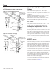
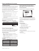
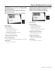
Tooperatethisunitwitha“manufacturer-approved”remote
thermostat,congurethecontroltobeoperatedbytheremote
thermostat.EntercongurationmodeC1andthenselectop-
tionCodeL5.Whenintheremotemode,theunitwillonly
respondtothethermostatinputs(terminalstrippositionsGL
(orGH),W2,Y/W1,andB*shownin“ControlBoardUser
Inputs”illustration).
Notes: Once conguration C1 with option code L5 has been
selected, the control touchpad will no longer accept
inputs other than conguration and diagnostics modes.
The room occupant must operate the unit at the
remote mounted thermostat.
In remote mode, the 3-minute compressor time delay,
the random restart feature and the freeze protection
feature are all active (see Unit Features section).
When remote wall-mounted thermostat is used, the
delay may be a total of 8-minutes.