
Engineering

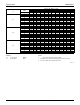
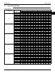

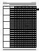


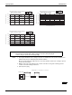

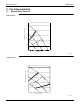
Table Of Contents

Capacity Tables EDUS181520C
62 Multi-Split Type Air Conditioners RMXS-L Series
Notes: 1. These figures illustrate the rate of change in capacity of a standard indoor unit system at maximum load
(with the thermostat set to maximum) under standard conditions.
Moreover, under partial load conditions there is only a minor deviation from the rate of change in capacity
shown in the above figures.
2. With this outdoor unit, evaporating pressure constant control when cooling, and condensing pressure
constant control when heating is carried out.
3. System layout of piping
95%
96%
97%
98%
99%
100%
Rate of Change in Capacity (%)
1.Refrigerant Piping Connection Diameter
liquid: φ 1/4 inch (φ 6.4 mm)
gas: φ 5/8 inch (φ 15.9 mm)
0 9.8 20 30 4940
Branch piping length: L2 (ft)
Cooling
Heating
90%
91%
92%
93%
94%
95%
96%
97%
98%
99%
100%
Rate of Change in Capacity (%)
2.Refrigerant Piping Connection Diameter
liquid: φ 1/4 inch (φ 6.4 mm)
gas: φ 1/2 inch (φ 12.7 mm)
0209.8 30 4940
Branch piping length: L2 (ft)
Cooling
Heating
88%
90%
92%
94%
96%
98%
100%
Rate of Change in Capacity (%)
3.Refrigerant Piping Connection Diameter
liquid: φ 1/4 inch (φ 6.4 mm)
gas: φ 3/8 inch (φ 9.5 mm)
0209.8 30 40 49
Branch piping length: L2 (ft)
Cooling
Heating
[Method of calculating cooling/heating capacity]
Total capacity from capacity tables × (Rate of change in capacity by main piping length
× Rate of change in capacity by branch piping length)
C: 3D080739
Piping length : L1 = 16.4 ft (5 m), L2 = 9.8 ft (3 m)
L2L1
BP unit Indoor unit
Outdoor unit
16.4 ft (5 m) 9.8 ft (3 m)