Air Purifier OPERATION MANUAL Floor Standing, Wall-hanging Type MODEL MC70LPVM 00_CV_3P276413-3C.
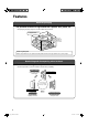
Features About air purifying The powerful suction of a high airflow rate captures dust, pollen, etc. • The purifying capacity improves as the airflow rate increases. The air permeates the room at a high airflow rate. Powerful suction from 3 directions llen Po Odour Dust Effective against pollen With the high airflow rate, even pollen that readily settles because of its large particle size is quickly caught. Deodorising and decomposing odour in the air The streamer discharge decomposes absorbed odour.
What is the “Streamer” function? This function uses a “streamer discharge”, a type of plasma discharge, to generate high-speed electrons with strong oxidation power inside the air purifier, reducing or removing odour swiftly. (The highspeed electrons are generated and absorbed within the unit to ensure your safety.) The hissing sound of the streamer discharge may be heard during operation. It does not indicate any operational issue.
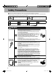
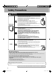
Safety Precautions Before use, read these Safety Precautions to ensure proper handling of equipment. The precautions used in this manual are classified into the following two types. Both contain important safety information, therefore observe them at all times. WARNING Improper handling may lead to serious injury or even death. CAUTION Improper handling may lead to injury or property damage. In some situations, the consequences may be grave. The icons used in this manual mean the following.
WARNING • Do not use combustible substances, i.e., hair spray, insecticides, etc., near the unit. Do not wipe the unit with benzene or thinner. These substances may lead to cracking, electric shock or ignition. • Use a neutral detergent to clean the unit. Use of chlorine or acidic detergents to clean the unit may generate harmful gas and harm health. Main unit • These servicing instructions are for use by qualified personnel only.
Safety Precautions CAUTION • Do not expose plants or animals to direct air currents from the unit. Overexposure to air currents may have adverse effects. • Keep fish tanks, vases and other water containers away from the unit. Water infiltration into the unit may lead to electric shock, fire or damage. • Do not climb, sit or lean on the unit. Falling or toppling over may lead to injury. • Do not remove the filter with the unit lying on its side.
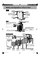
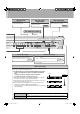
Name and Operation of Each Part Front Unit display Receiver ►Page 7. Air inlet for air quality sensor (dust sensor) Air inlet for odour sensor ►Page 16. ►Page 16. Front panel Air inlet ►Page 15. Rear Handles Air outlet Remote controller storage slot Stores the accessory remote controller when not in use. Remote controller Power supply cord hook Can be used for winding the extra part of the power supply cord. ►Page 12.
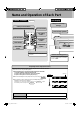
Name and Operation of Each Part Remote controller Unit display ►Page 13, 14. Child proof lock lamp (orange) Child proof lock button It prevents small children from mishandling the unit. ON / OFF button Auto fan lamp (yellow) Fan setting button Auto fan button Anti-pollen button Turbo button Sleep mode button OFF TIMER button Brightness adjustment button The brightness of the unit display lamp can be adjusted.
Operation lamp ON / OFF / Mode change button • Turbo lamp (orange) • Anti-pollen lamp (green) • Sleep mode lamp (green) The operation mode changes each time the button is pressed. ►Page 14. Filter reset button The filter lamp is turned off by pressing the button for 5 seconds after the pleated filter is replaced with a new one. ►Page 21.
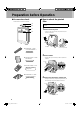
Preparation before Operation Accessories check How to attach the pleated filter Confirm all the accessories are included. A B C D Make sure to attach the pleated filter before starting operation. 1 Remove the front panel. • Push the 2 clips (right and left), and pull the front panel upward and remove it. Push Clip (1 each on right and left) Front panel A: Pleated filter…1 sheet < For initial installation > Inside cushion 2 Remove UNIT1.
4 Attach the pleated filter. Make sure to set the prefilter (green) and the pleated filter (front: white, rear: blue) in place. If you operate the unit without them, the unit may be damaged. 6 Attach UNIT1. • Holding UNIT1 by the handles, fit the projections into the grooves (2 locations) at the bottom of the main unit, and press UNIT1 into the main unit.
Preparation before Operation Installation of the unit Installed on a table or the floor CAUTION 100cm from ceiling • The wall where the air purifier is set may get dirty depending on the type of wall and environment, even if you follow the specified dimensions of left. In such cases, move the unit a safe distance away from the wall. • If the air purifier is used for a long time at the same location, the bottom of the unit and floor may become dirty due to the suction air flow from the bottom of the unit.
Preparation of remote controller A battery is already set in the remote controller. Insert the power plug into an electrical socket. • The remote controller can be used only after pulling out the clear sheet. Electrical socket Power plug Clear sheet You can adjust the length of the power supply cord by rolling up the extra part. Battery replacement 1 Move the tab of the cover on the rear of the remote controller in the direction of the arrow. 2 Pull out the cover. 3 Replace the battery.
How to Operate To start the operation Press . (Example of the initial display) • Operation starts and the airflow rate lamp lights up. during operation, operation stops. • When you press next time, operation starts with • When you press the same settings as the previous operation. To prevent mishandling by small children Childproof lock • Press for about 2 seconds to engage the childproof lock. again for • You can release the childproof lock by pressing about 2 seconds.
Operation with the button on the unit Press . • The operation mode changes each time the button is pressed. “ (Auto fan)” “ “Stop” “ (Sleep mode)” (Quiet)” “ “ (Low)” (Anti-pollen)” “ “ (Standard)” (Turbo)” “ (High)” ATTENTION • Operation stops for safety when the front panel is opened during operation.
Quick Reference Table of Maintenance WARNING Before performing maintenance, stop the unit and disconnect the power plug. (It may cause electric shock or injury.) Remove the parts for maintenance in numerical order. For details on removing and attaching each part, see ►Page 17. . Opposing pole plates Ionising frame Ionised wire 1 Front panel 2 Prefilter 3 UNIT1 (Plasma ioniser) 4 UNIT2 (Streamer unit) The figure above shows UNIT1 after the opposing pole plates are removed.
5 6 Pleated filter Deodorising catalyst unit 7 Main unit or air inlet for sensor Deodorising catalyst unit Pleated filter Air inlet for odour sensor Do not rinse with water. Face the white side to the front. If the filter lamp lights up or blinks Air inlet for air quality sensor Do not rub the front surface. About once a month, or if the odour or marking is a concern If it is clogged Vacuum cleaner Vacuum cleaner Replace Wipe Can not be rinsed in water Replacement ►Page 21.
Removing and Attaching Each Part Remove Attach 1 Remove the front panel. 1 Attach the deodorising catalyst unit. • Push the 2 clips (right and left), and pull the front panel upward and remove it. • Holding the deodorising catalyst unit by the handles, fit the projections into the grooves (4 locations) at the bottom of the main unit and, press the deodorising catalyst unit into the main unit. Handles Push Clip (1 each on right and left) Front panel 2 Remove the prefilter.
Removing and attaching the opposing pole plates CAUTION Wear rubber gloves to remove and attach the opposing pole plates. Hands can be cut on the opposing pole plates and ionised wires. Attach 1 Attach the opposing pole plates. UNIT1 1) Fit the opposing pole plate over the knobs (2 sets on the right and left) on the ionising frame. The opposing pole plates have no difference between the upper and the lower, or between the right and the left. Attach them so that the arrow is visible.
Cleaning of UNIT1 and UNIT2 Time for cleaning Cleaning method UNIT1: If the “UNIT1” lamp lights UNIT2: Once every 3 months or if the “UNIT2” lamp lights Soak, drain and dry UNIT1 UNIT2 (Plasma ioniser) (Streamer unit) Ionising frame Streamer unit Wipe If marking is a concern, clean the unit even if the “UNIT1” and “UNIT2” lamps do not light. For details on removing and attaching each part, see ►Page 17. .
CAUTION Wear rubber gloves when wiping or rubbing the units. • Hands can be cut on the opposing pole plates, ionised wires and needles of streamer unit. There are ionised wires on the rear of the opposing pole plates. Be careful not to snap these wires when removing and attaching the units. • If the unit is operated with broken ionised wires, the “UNIT1” lamp lights. While the lamp is lit, dust collecting capacity is low.
Replacement of the Pleated Filter 5 Press the filter reset button on the upper When the filter lamp in the display lights up or blinks Time for cleaning part of the front panel for 5 seconds. (The filter lamp goes off with a short beep sound.) It is not necessary to replace the pleated filter until the filter lamp lights up or blinks.
Sensitivity Setting of the Air Quality Sensor (dust sensor) The sensitivity of the air quality sensor can be changed. ON / OFF / Mode change button Airflow rate lamp 1 Press on the unit for 10 seconds. 2 With press pressed, point the remote controller at the unit and . • The receiving tone sounds, one of the airflow rate lamps “ (Low)”, “ (Standard)” or “ blinks for 5 seconds, and then the lamp corresponding to the set sensitivity lights up. 3 Change the sensitivity using (High)” on the unit.
Frequently Asked Questions Before consulting your dealer, check the following points. Question : Can the deodorising catalyst unit be washed with water? Does the unit need to be replaced? Answer : No, the deodorising catalyst unit can not be washed with water. (If the unit is washed with water, it will be deformed and become unusable.) When you have washed the deodorising catalyst unit by mistake, consult your dealer. Remove the unit from the main body, and use a vacuum cleaner to remove the dust.
Troubleshooting Before consulting your dealer or asking for repairs, check the following points. If the problems still can not be solved, consult your dealer. The unit does not operate. ● Is the front panel correctly set? The unit does not operate even if the ON / OFF button is pressed. ►Page 10. ● Are the projections on the rear of the front panel broken? Î Check the projections. ►Page 16. Consult your dealer if the projections are broken. ● Is the battery of the remote controller run down? ►Page 12.
Troubleshooting Before consulting your dealer or asking for repairs, check the following points. If the problems still can not be solved, consult your dealer. A sound is heard. A crackling or buzzing sound is heard during operation. ● Are UNIT1 and UNIT2 correctly set? Î Insert UNIT1 until it clicks. Insert UNIT2 completely to the end. ● Is dust adhered to UNIT1 and UNIT2? A fizzing sound is heard during operation. ►Page 17-20. ►Page 19, 20.
MEMO 26 01_EN_3P276413-3C.
Two-dimensional bar code is a code for manufacturing. 3P276413-3C M10B195B 00_CV_3P276413-3C.