English Français INSTALLATION MANUAL R410A Split Series Español DAIKIN ROOM AIR CONDITIONER Installation manual Manuel dinstallation Manual de instalación MODELS RX09NMVJU RX12NMVJU RX18NMVJU RX24NMVJU RXN09NMVJU RXN12NMVJU RXN18NMVJU RXN24NMVJU 00_CV_3P379970-6B.
Contents Safety Considerations .................................... 1 3. Flaring the pipe end..................................................... 6 4. Refrigerant piping ........................................................ 6 Accessories ..................................................... 3 5. Pressure test and evacuating system .......................... 7 6. Refilling refrigerant ...................................................... 8 Precautions for Selecting a Location ...........
• Make sure that all wiring is secured, that specified wires are used, and that no external forces act on the terminal connections or wires. Improper connections or installation may result in fire. • When wiring, position the wires so that the electrical wiring box cover can be securely fastened. Improper positioning of the electrical wiring box cover may result in electric shock, fire, or the terminals overheating. • Before touching electrical parts, turn off the unit.
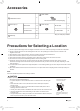
Accessories B Drain socket* 1 A Installation manual 1 This is at the bottom of the packaging. C Drain cap (1)* 09/12 class 4 15/18/24 class 6 E Warranty D Drain cap (2)* 1 09/12 class 2 15/18/24 class 3 *Only for heat pump models. Precautions for Selecting a Location 1) Choose a place solid enough to bear the weight and vibration of the unit, where the operating sound will not be amplified.
English Precautions on Installation 3/4” (20mm) • Check the strength and level of the installation surface so that the unit does not cause any operating vibrations or noise after installation. • Fix the unit in place securely using foundation bolts, as in the figure. (Prepare 4 sets of 5/16 inch (M8) or 3/8 inch (M10) foundation bolts, nuts and washers; all separately available.) • It is best to screw in the foundation bolts until their ends are 3/4 inch (20mm) from the foundation surface.
Installation Space Requirements • Where a wall or other obstacle is in the path of the outdoor unit’s intake or exhaust airflow, follow the installation space requirements below. • For any of the below installation patterns, the wall height on the outlet side should be 47-1/4 inch (1200mm) or less.
Drain work (only for heat pump models, excluding RXL models) 09/12 class 15/18/24 class C Drain cap (1) C Drain cap (1) D Drain cap (2) D Drain cap (2) CAUTION C Drain cap (1) In cold areas, do not use a drain socket, drain caps (1,2) and a drain hose with the outdoor unit. (Drain water may freeze, impairing heating performance.
Outdoor Unit Installation 5. Pressure test and evacuating system WARNING • • • • Do not mix any substance other than the specified refrigerant (R410A) into the refrigeration cycle. If refrigerant gas leaks should occur, ventilate the room as soon and as much as possible. R410A, as well as other refrigerants, should always be recovered and never be released directly into the environment. Use a vacuum pump for R410A exclusively.
English 6. Refilling refrigerant Check the type of refrigerant to be used on the machine nameplate. Precautions when adding R410A Fill from the liquid pipe in liquid form. R410A is a mixed refrigerant, so adding it in gas form may cause the refrigerant composition to change, preventing normal operation. 1) Before filling, check whether the cylinder has a siphon attached or not. (It should have something like “liquid filling siphon attached” displayed on it.
Wiring WARNING • Do not use tapped wires, extension cords, or starburst connections, as they may cause overheating, electric shock, or fire. • Do not use locally purchased electrical parts inside the product. (Do not branch the power for the drain pump, etc., from the terminal block.) Doing so may cause electric shock or fire. • Be sure to install a ground fault circuit interrupter. (One that can handle higher harmonics.) (This unit uses an inverter.
English 15/18/24 class [Method of mounting conduit] 1) Dismount the service lid by removing the 2 screws. 2) Pass wires through the conduit and secure them with a lock nut. 3) After completing the work, reattach the service lid to its original position. 1 2 3 Power supply terminal block Service lid 1 2 3 Shape wires so that the protection plate and conduit mounting plate fit securely.
Facility Setting* (cooling at low outdoor temperature) This function is limited only for facilities (the target of air conditioning is equipment (such as computer)). Never use it in a residence or office (the space where there is a human). *Only for RX, RK, and RXL models. Cutting jumper 6 (J6) on the circuit board will expand the operation range down to 5°F (–15°C). However it will stop if the outdoor temperature drops below –4°F (–20°C) and start back up once the temperature rises again.
1. English Trial Operation and Testing Trial operation and testing • Trial operation should be carried out in either COOL or HEAT operation. 1-1. Measure the supply voltage and make sure that it is within the specified range. 1-2. In COOL operation, select the lowest programmable temperature; in HEAT operation, select the highest programmable temperature. 1-3.
Two-dimensional bar code is a manufacturing code. 3P379970-6B M15B135 (1511) 00_CV_3P379970-6B.