INSTALLATION AND OPERATION MANUAL System Air Conditioner RXYQQ8T7Y1B RXYQQ10T7Y1B RXYQQ12T7Y1B RXYQQ14T7Y1B RXYQQ16T7Y1B RXYQQ18T7Y1B RXYQQ20T7Y1B
1 9 R7T 8 7 R6T 8 (S1NPL) (S1NPH) R3T HPS (S4PH) 10 HPS (S1PH) R3T HPS (S3PH) R21T 12 6 INV R8T 10-12HP M1C sv 17 10 sv sv 1 11 10 HPS (S1PH) R21T 6 3 (S1NPH) (S1NPL) HPS (S2PH) HPS (S3PH) 1 11 12 sv 18 16 1 3 2 6 12 10 3 4 6 14 10 12 10 3 15 4 15 4 4 5 5 14 14 8 8 7 7 17 17 18 18 11 3 16 1 11 4 16 2 13 HPS (S2PH) R22T 2 INV R8T 10-12HP M2C INV M1C 17 18 16 M 5 M2F R7T 14 14 4 M 5 M1F R4T R5T 3 R1T 4 18 sv 7 R6T R5
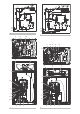
CE - DECLARACION-DE-CONFORMIDAD CE - DICHIARAZIONE-DI-CONFORMITA CE - ∆HΛΩΣΗ ΣΥΜΜΟΡΦΩΣΗΣ CE - ERKLÆRING OM-SAMSVAR CE - ILMOITUS-YHDENMUKAISUUDESTA CE - PROHLÁŠENÍ-O-SHODĚ 01 *** Daikin Europe N.V. is authorised to compile the Technical Construction File. 02 *** Daikin Europe N.V. hat die Berechtigung die Technische Konstruktionsakte zusammenzustellen. 03 *** Daikin Europe N.V. est autorisé à compiler le Dossier de Construction Technique. 04 *** Daikin Europe N.V.
declaración: заявление: 06 • Pressione massima consentita (PS): (bar) • Temperatura minima/massima consentita (TS*): * TSmin: temperatura minima nel lato di bassa pressione: (°C) * TSmax: temperatura satura corrispondente alla pressione massima consentita (PS): (°C) • Refrigerante: • Impostazione del dispositivo di controllo della pressione: (bar) • Numero di serie e anno di produzione: fare riferimento alla targhetta del modello 07 • Mέγιστη επιτρεπόμενη πίεση (PS): (bar) • Ελάχισ
RXYQQ8T7Y1B RXYQQ10T7Y1B RXYQQ12T7Y1B RXYQQ14T7Y1B RXYQQ16T7Y1B RXYQQ18T7Y1B RXYQQ20T7Y1B VRV IV System Air Conditioner Installation manual Contents Installation and operation manual 15. Start-up and configuration........................................................ 36 15.1. 15.2. 15.3. 15.4. 15.5. Page Installation manual .......................................................................... 1 1. Definitions ..................................................................................
Some types of danger are represented by special symbols: Electric current. 2. The precautions listed here are divided into the following four types. They all cover very important topics, so be sure to follow them carefully. Danger of burning and scalding. 1.2. General safety precautions DANGER: ELECTRICAL SHOCK Switch off all power supply before removing the electrical component box service panel or before making any connections or touching electrical parts.
The outdoor unit is designed to work in heating mode at ambient temperatures from –20°C to 21°C and in cooling mode at ambient temperatures from –5°C to 43°C. INFORMATION A combination of R410A VRV DX indoor units with non-R410A VRV DX indoor units will block the system. Such combinations cannot be used. Either all VRV DX indoor units are non-R410A type (as listed above) or R410A type. NOTICE Design of the system must not be done at temperatures below –15°C. 3.2.2.
4 To instruct specific operation with an external input coming from a central control the external control adaptor (DTA104A61/62) can be used. Instructions (group or individual) can be instructed for low noise operation and power consumption limitation operation 5 For VRV IV replacement heat pump system it is also possible to make several commissioning field settings through a personal computer interface.
See location 1 in the figure above for reference to where following accessories are supplied with the unit. Accessory pipes (mm) 8 HP Øa 10 HP Øb Øa Øb 12 HP Øa Øb Gas pipe 19.1 ID Øb 25.4 22.2 25.4 20 HP Øa Øb 25.4 28.6 25.4 28.6 12.7 15.9 12.7 15.9 Gas pipe Front connection ID Øa Front connection ID Øa Accessory pipes (mm) ID Øb 28.6 Bottom connection ID Øa OD Øb Bottom connection ID Øa OD Øb 19.1 25.4 22.2 25.4 28.
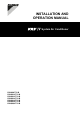
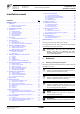
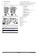
5. 5.1. Overview of unit 5.2. For all the models a piping diagram and outlook drawing are available. Depending on the model type some components in the main component list may not be existing in the unit.
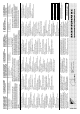
5.3. Main components in the electrical component box CAUTION Appliance not accessible to the general public, install it in a secured area, protected from easy access. RXYQQ8~12 This appliance is intended to be used by expert or trained users in shops, in light industry and on farms, or for commercial use by lay persons. 1 3 6.1.
6.2. The refrigerant R410A itself is nontoxic, non-flammable and is safe. If the refrigerant should leak however, its concentration may exceed the allowable limit depending on room size. Due to this, it could be necessary to take measures against leakage. Refer to "18. Caution for refrigerant leaks" on page 47. Do not install in the following locations: - Locations where sulphurous acids and other corrosive gases may be present in the atmosphere.
7. Dimensions and service space 7.1. Service space The space around the unit is adequate for servicing and the minimum space for air inlet and air outlet is available (refer to the figure below and choose one of the possibilities). Dimensions of outdoor unit RXYQQ8~12 7.2. 766 b b 729 c aa e aa d c e d 4-15x22.
The installation space required on these drawings are for full load heating operation without considering possible ice accumulation. If the location of the installation is in a cold climate, then all dimensions above should be >500 mm to avoid accumulation of ice in between the outdoor units. INFORMATION 8.3. Unpacking CAUTION To avoid injury, do not touch the air inlet or aluminium fins of the unit.
4 3 6 7 1 2 9. 5 AB Refrigerant pipe size and allowable pipe length AA General information NOTICE 929 729 9.1. The refrigerant R410A requires strict cautions for keeping the system clean, dry and tight. Clean and dry: foreign materials (including mineral oils or moisture) should be prevented from getting mixed into the system.
9.3. Selection of piping size 9.3.3. Determine the proper size referring to following tables and reference figure (only for indication). Piping between refrigerant branch kit and indoor unit: E Pipe size for direct connection to indoor unit must be the same as the connection size of the indoor unit. Piping outer diameter size (mm) Indoor unit capacity index A a B C y x B B D b Gas pipe Liquid pipe 15, 20, 25, 32, 40, 50 12.7 6.4 63, 80, 100, 125 15.9 200 19.1 250 22.
In case the required pipe sizes (inch sizes) are not available, it is also allowed to use other diameters (mm sizes), taken the following into account: - Select the pipe size nearest to the required size. - Use the suitable adapters for the change-over from inch to mm pipes (field supply). In this case, the additional refrigerant calculation has to be adjusted as mentioned in "14. Charging refrigerant" on page 30. 9.5. System piping (length) limitations 9.5.1.
9.5.2. System containing VRV DX indoor units System setup Branch with refnet joint and refnet header Branch with refnet joint Branch with refnet header Single outdoor i a b a A c d B h C i 1 e D j 2 E k 3 g f F l 4 G m 5 p n 6 A c 7 H2 d 1 8 k j e 2 a B b H1 H1 g f 3 4 7 8 H2 h 5 H1 b 1 6 d c 2 e 3 4 Example 1.2 Example 1.1 f g 5 h 6 i 7 H2 Example 1.
Increase the pipe size as follows: 9.5 → 12.7; 12.7 → 15.9; 15.9 → 19.1; 19.1 → 22.2; 22.2 → 25.4(3); 28.6 → 31.8(3); 34.9 → 38.1(3) Example: unit 8: b+c+d+e+f+g+p≤90 m and b+c+d+e+f+g >40 m; increase the pipe size of b, c, d, e, f, g. c. d. When the piping size is increased (step b), the piping length has to be counted as double (except for the main pipe and the pipes that are not increased in pipe size). The total piping length has to be within limitations (see table above).
Example: passing piping out through the front. NOTICE There are restrictions on the refrigerant pipe connection order between outdoor units during installation in case of a multiple outdoor unit system. Install according to following restrictions. The capacities of outdoor units A, B and C must fulfill the following restriction conditions: A≥B≥C. A 1 2 B C 1 Use clean pipes only. Hold the pipe end downwards when removing burrs.
10.2. Connecting the refrigerant piping 2 Connect the vacuuming/recovery unit to service ports of all stop valves. 6 NOTICE Installation shall be done by an installer, the choice of materials and installation shall comply with the applicable legislation. In Europe, EN 378 is the applicable standard that shall be used.
7 Cut the pinched piping off with a pipe cutter just above the brazing point or marking if there is no brazing point. 10.2.4. Branching the refrigerant piping WARNING For installation of the refrigerant branching kit, refer to the installation manual delivered with the kit. Never remove the pinched piping by brazing. Any gas or oil remaining inside the stop valve may blow off the pinched piping.
10.3. Guidelines for handling stop valve 10.3.1. Cautions on handling the stop valve Make sure to keep both stop valves open during operation. The figure below shows the name of each part required in handling the stop valve. The stop valve is factory closed. 10.3.3. Cautions on handling the stop valve cover The stop valve cover is sealed where indicated by the arrow. Take care not to damage it. After handling the stop valve, make sure to tighten the stop valve cover securely.
10.4.1. General guidelines Use a 2-stage vacuum pump with a non-return valve which can evacuate to a gauge pressure of –100.7 kPa (5 Torr absolute, –755 mm Hg). Connect the vacuum pump to the service port of all stop valves to increase efficiency (refer to "10.4.4. Setup" on page 20). 10.4.4. Setup 6 1 NOTICE Do not purge the air with refrigerants. Use a vacuum pump to evacuate the installation.
NOTICE Make sure to use a recommended bubble test solution from your wholesaler. Do not use soap water, which may cause cracking of flare nuts (soap water may contain salt, which absorbs moisture that will freeze when the piping gets cold), and/or lead to corrosion of flared joints (soap water may contain ammonia which causes a corrosive effect between the brass flare nut and the copper flare.
WARNING A main switch or other means for disconnection, having a contact separation in all poles, must be incorporated in the fixed wiring in accordance with the applicable legislation. Use only copper wires. All field wiring must be carried out in accordance with the wiring diagram supplied with the unit and the instructions given below. Never squeeze bundled cables and be sure that it does not come in contact with the non-insulated piping and sharp edges.
K4R........................ Magnetic relay (Y2S) WHT ...................... White K5R........................ Magnetic relay (Y4S) YLW ....................... Yellow K6R........................ Magnetic relay (Y5S) K7R........................ Magnetic relay (E1HC) Connector for optional accessories: K8R........................ Magnetic relay (E2HC) X14A...................... Connector (drain pan heater) K10R...................... Magnetic relay (option) X37A......................
12.6. Routing 1 2 It is important to keep the power supply and the transmission wiring separated from each other. In order to avoid any electrical interference the distance between both wiring should always be at least 25 mm. 3 4 5 1 2 3 4 5 12.6.1. Transmission wiring routing The transmission wiring outside the unit should be wrapped and routed together with the field piping.
1 2 3 4 5 Liquid pipe Gas pipe Insulator Transmission wiring (F1/F2) Finishing tape RXYQQ14~20 7 For the above wiring, always use vinyl cords with 0.75 to 1.25 mm2 sheath or cables (2-core wires). (3-core wire cables are allowable for the cooler/heater changeover user interface only.) 6 2 NOTICE Be sure to keep the power line and transmission line apart from each other. Transmission wiring and power supply wiring may cross, but may not run parallel.
Front side. In order to route the power supply from the front side, the available knockout holes (C) can be used: RXYQQ14~20 Fix the power supply cable to the foreseen wire clips with a tie wrap. See figures below, item 2. Fix the power supply cable to the heat exchanger fixing plate (through oblong hole). See figures below, item 2. X1M Front plate: possible power supply wire entrance hole (close hole to avoid bugs/dirt from entering). See figures below, item 3.
12.7. Connection 12.7.2. Connection of wiring to terminals This chapter gives an explanation how to route and connect the wiring within the unit. Transmission wiring in outdoor unit 1 2 3 2 3 12.7.1.
7 Earth wire (GRN/YLW) 8 Clamp the power supply to the plastic bracket using a field supplied clamp to prevent external force being applied to the terminal. 9 Clamp (field supplied) 10 Cup washer 11 When connecting the earth wire, it is recommended to perform curling. INFORMATION Connecting the power supply to multiple outdoor units To connect the power supply for multiple outdoor units to each other, ring tongues have to be used. No bare cable can be used.
Location of the segment displays, buttons and DIP switches: 1 2 When above situation cannot be confirmed after 12 min, the malfunction code can be checked on the indoor unit user interface and the outdoor unit segment display. Solve the malfunction code accordingly. The communication wiring should be checked at first. INFORMATION DS1 DS2 BS1 BS2 BS3 Be sure to turn the power on at least 6 hours before operation in order to have power running to the crank case heater.
Mode 2 is used to set field settings of the outdoor unit and system. Changing and access the setting in mode 2: Once mode 2 is selected (push BS1 for more than 5 seconds), you can select the wanted setting. It is done by pushing BS2. Accessing the selected setting's value is done by pushing BS3 1 time. To quit and return to the initial status, press BS1.
14.2. Important information regarding the refrigerant used This product contains fluorinated greenhouse gases covered by the Kyoto Protocol. Do not vent gases into the atmosphere.
14.4. Method for adding refrigerant INFORMATION If it is not possible to determine exact piping lengths of the existing field piping, it is difficult to calculate the additional refrigerant charge exactly as explained above. In such a case, make an estimation based on the known lengths and diameters by using the formula as in "14.3.1.
<< Continuation of previous page << Continuation of previous page Heating charging ("t22" startup control) ("t23" waiting for stable heating) Cooling charging ("t02" startup control) ("t03" waiting for stable cooling) "t23" is flashing • Push BS2 within 5 minutes • Open valve A "t03" is flashing • Push BS2 within 5 minutes • Open valve A Display show "t03" and low pressure value with an interval of 1 second. Refrigerant will be charged automatically.
CAUTION When charging a system, charging over permissible quantity can cause liquid hammer. the Always use protective gloves and protect your eyes when charging refrigerant. When the refrigerant charging procedure is done or when pausing, close the valve of the refrigerant tank immediately. If the tank is left with the valve open, the amount of refrigerant which is properly charged may get off point. More refrigerant may be charged by any remaining pressure after the unit has stopped.
INFORMATION For a multi outdoor unit system, it is not required to connect all charge ports to a refrigerant tank. The refrigerant will be charged with ±22 kg in 1 hour time at an outdoor temperature of 30°C DB or with ±6 kg at an outdoor temperature of 0°C DB. If you need to speed up in case of a multiple outdoor system, connect the refrigerant tanks to each outdoor unit. NOTICE The refrigerant charging port is connected to the piping inside the unit.
Perform the test procedure as described in "15.4. Test operation" on page 43. B. 15. Start-up and configuration Adding refrigerant by using the manual charging function INFORMATION 6B The remaining additional refrigerant charge can be charged by operating the outdoor unit by means of the manual refrigerant charge operation mode: It is important that all information in this chapter is read sequentially by the installer and that the system is configured as applicable.
14 15 Additional refrigerant charge The amount of refrigerant to be added to the unit shall be written on the included "Added refrigerant" plate and attached to the rear side of the front cover. [1-2]= Installation date and field setting Be sure to keep record of the installation date on the sticker on the rear of the upper front panel according to EN60335-2-40 and keep record of the contents of the field setting(s).
15.2.2. Mode 2 Change [2-9]=0, 1, 3 or 6 in function of required operation method during heating. Mode 2 is used to change the field settings of the system. Consulting the current field setting value and changing the current field setting value is possible. In general, normal operation can be resumed without special intervention after changing field settings. For more information and advice about the impact of these settings, see "15.3. Energy saving and optimum operation" on page 40.
[2-25]= Low noise operation level via the external control adaptor [2-31]= If the system needs to be running under low noise operation conditions when an external signal is sent to the unit, this setting defines the level of low noise that will be applied (3: Level 3<2: Level 2<1: Level 1). Power consumption limitation level (step 2) via the external control adaptor (DTA104A61/62).
[2-82]= Heating comfort setting. Default value=1 Value [2-82] Heating comfort setting 0 Eco 1 Mild (default) 2 Quick 3 Powerful To activate this setting under cooling operation: change field setting [2-8] to the appropriate value, matching the requirements of the pre-designed system containing a high sensible solution. Change [2-82]=0, 1, 2 or 3 in function of required limitation. This setting is used in conjunction with setting [2-9].
Quick Overshoot (during heating operation) or undershoot (during cooling operation) is allowed compared to the requested refrigerant temperature, in order to achieve the required room temperature very fast. The overshoot is allowed from the start up moment. In case of cooling operation the evaporating temperature is allowed to go down to 6°C on temporary base depending on the situation.
Example: Automatic mode during cooling Example: Automatic mode during heating E E 100% 100% A B A 70% 50% B Te Tc 49°C C D C 46°C 6°C 3°C 35°C F D A Actual load curve B Virtual load curve (initial capacity automatic mode) C Virtual target value (initial evaporation temperature value automatic mode) D Required evaporation temperature value E Load factor F Outside air temperature Te Evaporating temperature Quick Powerful Mild 2°C F A Virtual load curve (default automatic mode peak capacity)
No matter which control is selected, variations on the behaviour of the system are still possible due to protection controls to keep the unit operating under reliable conditions. The intentional target, however, is fixed and will be used to obtain the best balance between energy consumption and comfort, depending on the application type. NOTICE To protect the compressor, be sure to turn on the power supply 6 hours before starting operation. 15.4.2. Test operation 15.4.
5 Check the test operation results on the outdoor unit segment display. - Normal completion: no indication on the segment display (idle) - Abnormal completion: indication of malfunction code on the segment display Refer to "15.4.3. Correcting after abnormal completion of the test operation" on page 44 to take actions for correcting the abnormality. When the test operation is fully completed, normal operation will be possible after 5 minutes. 15.4.3.
Malfunction code Main code JA Sub code Master/slave 1/slave 2 Contents Solution 06/08/10 High pressure sensor malfunction (S1NPH): open circuit A1P (X32A) Check connection on PCB or actuator 07/09/11 High pressure sensor malfunction (S1NPH): short circuit A1P (X32A) Check connection on PCB or actuator 06/08/10 Low pressure sensor malfunction (S1NPL): open circuit - A1P (X31A) Check connection on PCB or actuator 07/09/11 Low pressure sensor malfunction (S1NPL): short circuit - A1P (X31A) Check
Information code Main code Contents Solution Auto charging related P2 Unusual low pressure on suction line Close valve A immediately. Push BS3 to reset. Check following items before retrying autocharge procedure: • Check if the gas side stop valve is opened correctly. • Check if the valve of the refrigerant cylinder is opened. • Check if the air inlet and outlet of the indoor unit are not obstructed. P8 Freeze-up prevention indoor unit Close valve A immediately. Push BS3 to reset.
1 Direction of the refrigerant flow 2 Room where refrigerant leak has occurred (outflow of all the refrigerant from the system) NOTICE Play it safe. For protection of the PCB, touch the switch box casing by hand in order to eliminate static electricity from your body before performing service. Pay special attention to places, such as basements etc., where refrigerant can stay, since refrigerant is heavier than air. 17.3. Service mode operation 18.3.
4 Calculate the refrigerant density taking the volume of the room where the indoor unit is installed and the adjacent room. Install ventilation openings in the door of adjacent rooms until the refrigerant density is smaller than the maximum concentration level.
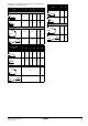
20.2. Electrical specifications RXYQQ8 RXYQQ10 RXYQQ12 RXYQQ14 Power supply • name Y1 • phase 3N~ • frequency • Voltage (Hz) 50 (V) 380-415 Current • nominal running current (RLA)(a) (A) • starting current (MSC)(b) (A) • minimum circuit amps (MCA)(c) (A) • Maximum fuse amps (MFA)(d) (A) • Total overcurrent amps (TOCA)(e) (A) • Full load amps (FLA)(f) (A) Voltage range 7.2 10.2 12.7 15.4 24.0 27.0 ≤MCA 16.1 22.0 20 25 32 17.3 24.6 1.2 1.3 35.4 1.5 1.
Operation manual 1. Definitions 1.1. Contents Page 1. Definitions................................................................................ 50 1.1. 1.2. Warnings in this manual are classified according to their severity and probability of occurrence. Meaning of warnings and symbols............................................... 50 Meaning of used terms ................................................................
Accessories: Equipment which is delivered with the unit and which needs to be installed according to instructions in the documentation. WARNING If you detect any abnormality such as smell of fire, turn off the power supply and call your dealer for instructions. Do not place objects in direct proximity of the outdoor unit and do not let leaves and other debris accumulate around the unit. Leaves are a hotbed for small animals which can enter the unit.
WARNING NOTICE Do not install the air conditioner at any place where flammable gas may leak out. If the gas leaks out and stays around the air conditioner, a fire may break out. Never put any objects into the air inlet or outlet. Objects touching the fan at high operating speed can be dangerous. In order to avoid electric shock or fire, make sure that an earth leak detector is installed. Be sure the air conditioner is electrically earthed.
2.2. 6. System layout Your VRV IV replacement heat pump series outdoor unit can be as follows: 1 5 2 3 Operation procedure Operation procedure varies according to the combination of outdoor unit and user interface. To protect the unit, turn on the main power switch 6 hours before operation. If the main power supply is turned off during operation, operation will restart automatically after the power turns back on again. 3 6.1. 4 1 2 3 4 5 3.
Adjustment Starting the system For programming temperature, fan speed and air flow direction refer to the operation manual of the user interface. 1 Press the operation mode selector button on the user interface several times and select (program dry operation). 2 Press the ON/OFF button of the user interface. The operation lamp lights up and the system starts operating. 3 Press the air flow direction adjust button (only for Double-flow, Multi-flow, Corner, Ceiling-suspended and Wall-mounted).
For the following conditions, a micro computer controls the air flow direction which may be different from the display. COOLING HEATING • When the room temperature is lower than the set temperature. • When starting operation. • When the room temperature is higher than the set temperature. 6.5. This system provides two other control systems beside individual control system (one user interface controls one indoor unit).
Three main operation methods are available: 8. The refrigerant temperature is fixed independent from the situation. It corresponds to the standard operation which is known and can be expected from/under previous VRV systems. Maintenance Basic CAUTION Pay attention to the fan. Automatic It is dangerous to inspect the unit while the fan is running. Be sure to turn off the main switch before executing any maintenance task.
Symptom 3: Fan operation is possible, but cooling and heating do not work Immediately after the power is turned on. The micro computer is getting ready to operate and is performing a communication check with all indoor units. Please wait 12 minutes (max.) till this process is finished. Symptom 8.2: Indoor unit, outdoor unit A continuous low hissing sound is heard when the system is in cooling or defrost operation. This is the sound of refrigerant gas flowing through both indoor and outdoor units.
10. Troubleshooting 11. After-sales service and warranty If one of the following malfunctions occur, take the measures shown below and contact your dealer. 11.1. Warranty period WARNING Stop operation and shut off the power if anything unusual occurs (burning smells etc.). Leaving the unit running under such circumstances may cause breakage, electric shock or fire. Contact your dealer.
11.4. Malfunction codes NOTICE 1 Table 1 indicates main components. Refer to your maintenance and inspection contract for more details. 2 Table 1 indicates recommended intervals of maintenance cycles. However, in order to keep the unit operational as long as possible, maintenance work may be required sooner. Recommended intervals can be used for appropriate maintenance design in terms of budgeting maintenance and inspection fees.
Malfunction code Main code Contents LC Transmission outdoor unit - inverter: INV transmission trouble P1 INV unbalanced power supply voltage P2 Autocharge operation related P4 Fin thermistor malfunction P8 Autocharge operation related P9 Autocharge operation related PE Autocharge operation related PJ Capacity setting malfunction (outdoor) U0 Abnormal low pressure drop, faulty expansion valve U1 Reversed power supply phase malfunction U2 INV voltage power shortage U3 System test run
0000000S* Copyright 2013 Daikin *4P345099-1 4P345099-1 2013.